Wellbore method and apparatus for sand and inflow control during well operations

a wellbore and inflow control technology, applied in the direction of wellbore/well accessories, drinking water installation, construction, etc., can solve the problems of increasing the individual well cost, increasing the difficulty of wellbore operation, and fewer wells being completed

Active Publication Date: 2011-07-26
EXXONMOBIL UPSTREAM RES CO
View PDF101 Cites 35 Cited by
  • Summary
  • Abstract
  • Description
  • Claims
  • Application Information

AI Technical Summary

Benefits of technology

In a seventh embodiment, a third apparatus for producing hydrocarbons is described. The apparatus includes a first tubular member having a permeable section and a non permeable section; a second tubular member disposed within the first tubular member, wherein the second tubular member has a plurality of openings and at least one inflow control device; and a sleeve disposed adjacent to the second tubular member and configured to move between a plurality of positions. The plurality of positions include a first position providing a first flow path into the interior of the second tubular member from the permeable section of the first tubular member through at least the plurality of openings; and a second position providing a second flow path into the interior of the second tubular member from the permeable section of the first tubular member through the at least one inflow control device, wherein fluid flow is prevented through the plurality of openings.

Problems solved by technology

However, when producing hydrocarbons from subsurface or subsurface formations, it becomes more challenging because of the location of certain subsurface formations.
As such, the location of the subsurface formation may present problems that increase the individual well cost dramatically.
That is, the cost of accessing the subsurface formation may result in fewer wells being completed because of the economics of the field.
The production of solid material may result in sand production at surface, downhole equipment damage, reduced well productivity and / or loss of the well.
Because gravel packing operations generally involve passing large quantities of fluid, such as carrier fluid, through the sand screen and the ICD, gravel packing with typical ICDs is not feasible because the gravel packing and production operations use the same flow paths.
In particular, localized and reduced inflow of the carrier fluid due to ICDs may cause early bridging, loose packs, voids, and / or increased pressure requirements during gravel pack pumping.

Method used


Image

  • Wellbore method and apparatus for sand and inflow control during well operations
  • Wellbore method and apparatus for sand and inflow control during well operations
  • Wellbore method and apparatus for sand and inflow control during well operations

Examples


Embodiment Construction

In the following detailed description section, the specific embodiments of the present invention are described in connection with preferred embodiments. However, to the extent that the following description is specific to a particular embodiment or a particular use of the present invention, this is intended to be for exemplary purposes only and simply provides a description of the exemplary embodiments. Accordingly, the invention is not limited to the specific embodiments described below, but rather, it includes all alternatives, modifications, and equivalents falling within the true spirit and scope of the appended claims.

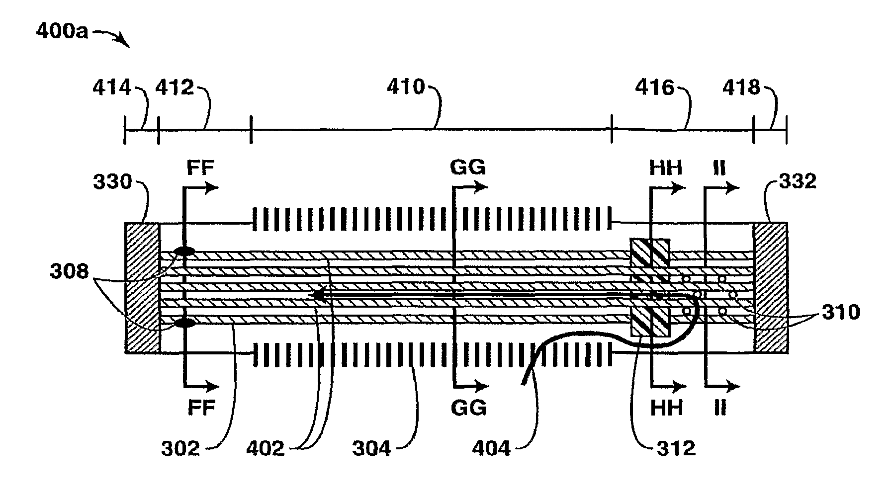
The present invention includes one or more embodiments of sand control devices that may be utilized in a completion, production, or injection system to enhance well operations, which may include gravel packing operations and production operations, which are described below. Under the present invention, an apparatus, system and method are described for running and ...


PUM


Abstract

A method, system and apparatus associated with the production of hydrocarbons are described. The system includes a wellbore that accesses a subsurface reservoir; a production tubing string disposed within the wellbore; and one or more sand control devices coupled to the production tubing string and disposed within the wellbore. At least one of the sand control devices includes a first tubular member having a permeable section and a non permeable section; a second tubular member disposed within the first tubular member. The second tubular member has a plurality of openings and an inflow control device that each provide a flow path to the interior of the second tubular member. Also, the at least one of the sand control devices includes a sealing mechanism disposed between the first tubular member and the second tubular member. The sealing mechanism is configured to provide a pressure loss during gravel packing operations that is less than the pressure loss during at least some of the production operations.

Description

FIELD OF THE INVENTIONThis invention relates generally to an apparatus and method for use in wellbores and associated with the production of hydrocarbons. More particularly, this invention relates to a wellbore apparatus and method for providing flow control that may be utilized to enhance at least gravel packing and production operations for a well.BACKGROUNDThis section is intended to introduce various aspects of the art, which may be associated with exemplary embodiments of the present invention. This discussion is believed to assist in providing a framework to facilitate a better understanding of particular aspects of the present invention. Accordingly, it should be understood that this section should be read in this light, and not necessarily as admissions of prior art.The production of hydrocarbons, such as oil and gas, has been performed for numerous years. However, when producing hydrocarbons from subsurface or subsurface formations, it becomes more challenging because of th...

Claims


Application Information

Patent Timeline
Patent Type & Authority Patents(United States)
IPC IPC(8): E21B43/04E21B43/08
CPCE21B33/12E21B43/08E21B43/04
Inventor HAEBERLE, DAVID C.YEH, CHARLESBENISH, TIMOTHY G.BARRY, MICHAEL D.HECKER, MICHAEL T.BLACKLOCK, JON
Owner EXXONMOBIL UPSTREAM RES CO
Why Eureka
Try Eureka