Two-side asymmetric light-shift illuminating lens body

a technology of light-shift illuminating and lens body, which is applied in the field of two-side asymmetric light-shift illuminating lens body, can solve the problems of reducing the efficiency of illuminating, reducing and insufficient energy around the light axis, so as to reduce the quantity of illuminating sources and reduce production costs

Inactive Publication Date: 2011-07-26
GENIUS ELECTRONICS OPTICAL CO LTD
View PDF6 Cites 22 Cited by
  • Summary
  • Abstract
  • Description
  • Claims
  • Application Information

AI Technical Summary

Benefits of technology

[0006]Accordingly, a primary object of the present invention is to provide a two-side asymmetric light-shift illuminating lens body capable of diffusely refracting rays from a center light axis of the lens body so as to generate two-side illuminating distribution. It can be applied to flat illuminating source and it can reduce the quantity of the illuminating source and lower cost of production.
[0007]To achieve above objects, the present invention provides a two-side asymmetric light-shift illuminating lens body with two asymmetrical non-spherical protrusions arranged to two sides of a center light axis of the lens body. A concave curved surface is formed to a border of the two asymmetric non-spherical protrusions. Two symmetrical cambered convex laterals are formed on relative outer edges of the non-spherical protrusions. Rays closed to the center light axis will be diffusely refracted to two sides away the center light axis with asymmetric directions by the concave curved surface and the rays will be further more diffusely refracted away from the center light axis by the non-spherical protrusions. By a refraction of light perpendicular to the center light axis through the cambered convex laterals, the light emitting device can project uniformly and asymmetrically on two lateral sides.

Problems solved by technology

However, the light is gathered around the light axis of the source so the light energy is too concentrated.
However, an illuminating efficiency will be lowered by multiple reflections and refractions of the structure, insufficient energy around the light axis is caused by too much rays being refracted perpendicular to the light axis.

Method used


Image

  • Two-side asymmetric light-shift illuminating lens body
  • Two-side asymmetric light-shift illuminating lens body
  • Two-side asymmetric light-shift illuminating lens body

Examples


Embodiment Construction

[0016]In order that those skilled in the art can further understand the present invention, a description will be provided in the following in details. However, these descriptions and the appended drawings are only used to cause those skilled in the art to understand the objects, features, and characteristics of the present invention, but not to be used to confine the scope and spirit of the present invention defined in the appended claims.

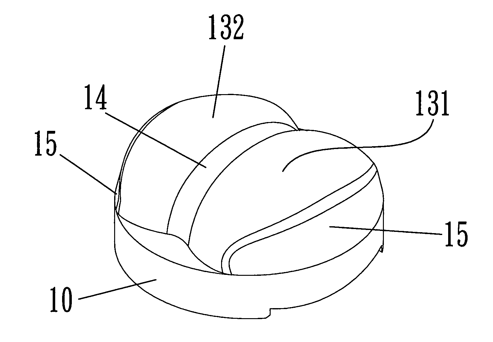
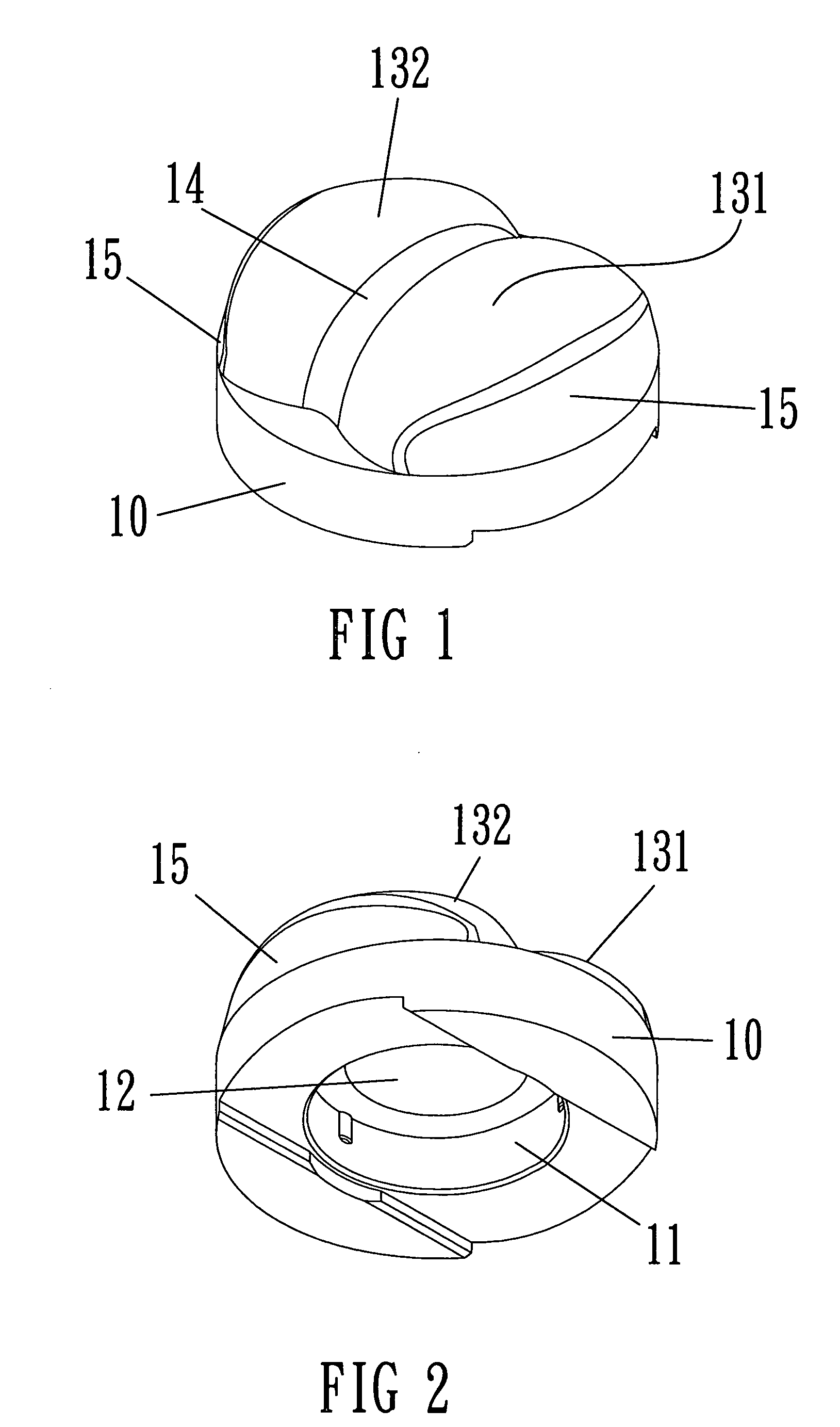
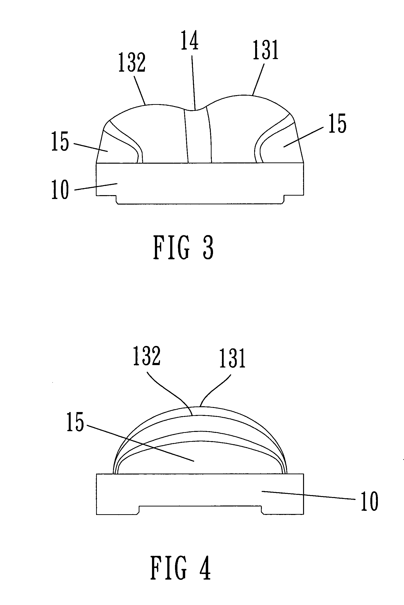
[0017]Firstly, referring to FIGS. 1 to 7, a preferable embodiment of two-side asymmetric illuminating lens body according to the present invention is illustrated. The lens body includes a highly transparent base 10 with a receiving slot 11 having a downwards opening for receiving and positioning a lighting, device 20. A concave arc 12 for receiving the light emitting portion of the lighting device 20A is formed above the receiving slot 11 as a light incident side. A top surface of the base 10 is arranged with a non-spherical large protrusion 131 an...


PUM


Abstract

A two-side asymmetric light-shift illuminating lens body mainly projecting light from a light emitting device to two asymmetric relative outer directions includes a base having a receiving slot with a downwards opening for receiving a lighting device; a large non-spherical protrusion and a small a large non-spherical protrusion being arranged on two sides of a center light axis on a top surface of the base; a concave curved surface being formed to a border of the two non-spherical protrusions; a concave arc is formed above the receiving slot, outer edge of each non-spherical protrusion being formed with a aft cambered convex lateral. The cambered convex laterals are gradually narrowed along the projecting direction of the center light axis. An angle between a tangent line of the cambered convex lateral and the center light axis is about 10 degrees.

Description

FIELD OF THE PRESENT INVENTION[0001]The present invention relates to lens body, and particular to lens body equipped with a light emitting device capable of generating two-side illumination by diffusely refracting rays from the light emitting device through at least three different refractions.DESCRIPTION OF THE PRIOR ART[0002]A prior lens is usually made with a Light Emitting Diode (LED) capsulated inside and with a spherical top for gathering and concentrating the light. However, the light is gathered around the light axis of the source so the light energy is too concentrated. To enlarge the illuminating area, light guiding plate is provided to solve the above problem. To overcome the small illuminating area of the LED, a plurality of LEDs is needed to achieve the uniformity as a flat illuminating source.[0003]Therefore, to efficiently reduce quantity of the LED under the certain area of guiding plate, inventors turn to develop lens for the purpose such as a patent no. U.S. Pat. N...

Claims


Application Information

Patent Timeline
Patent Type & Authority Patents(United States)
IPC IPC(8): F21V5/04
CPCF21V5/04G02B27/0955G02B19/0071G02B19/0014G02B19/0061F21W2131/103F21Y2101/02F21Y2115/10
Inventor HO, YEN-WEI
Owner GENIUS ELECTRONICS OPTICAL CO LTD
Why Eureka
Try Eureka