
System and method for generating self-synchronized launch of last shift capture pulses using on-chip phase locked loop for at-speed scan testing

a technology of phase lock loop and capture pulse, which is applied in power supply testing, instruments, measurement devices, etc., can solve the problems of cross talk, high impedance metal, and high impedance shorts of integrated circuit manufacturers, and achieve the effect of reducing the number of defects, and reducing the number of capture pulses

Inactive Publication Date: 2011-07-26
AVAGO TECH INT SALES PTE LTD
View PDF4 Cites 13 Cited by
  • Summary
  • Abstract
  • Description
  • Claims
  • Application Information

AI Technical Summary

Benefits of technology

The patent describes a system and method for generating self-synchronized launch of last shift capture pulses using a phase locked loop for at-speed scan testing. This technology allows for more efficient and accurate testing of electronic devices.

Problems solved by technology

In very deep sub-micron designs, integrated circuit manufacturers are starting to see more defects that are not caught by traditional stuck-at-fault testing.
Defects like high impedance metal, high impedance shorts, cross talk that may not be caught by traditional stuck at scan vectors show up as timing failures that are caught by at-speed testing.
Running a small number of functional vectors can be time consuming and may produce poor coverage.
Relying on ATE for at-speed capture pulses does not guarantee good yield for the needed tester accuracy in high speed integrated circuits.
It is also possible that because of testing inaccuracy some good parts would fail the at-speed test.
Multiple clock frequency further complicate matters.
Sometimes, the testing will not support all the required capture pulses at the different frequencies.

Method used


Image

  • System and method for generating self-synchronized launch of last shift capture pulses using on-chip phase locked loop for at-speed scan testing
  • System and method for generating self-synchronized launch of last shift capture pulses using on-chip phase locked loop for at-speed scan testing
  • System and method for generating self-synchronized launch of last shift capture pulses using on-chip phase locked loop for at-speed scan testing

Examples


Embodiment Construction

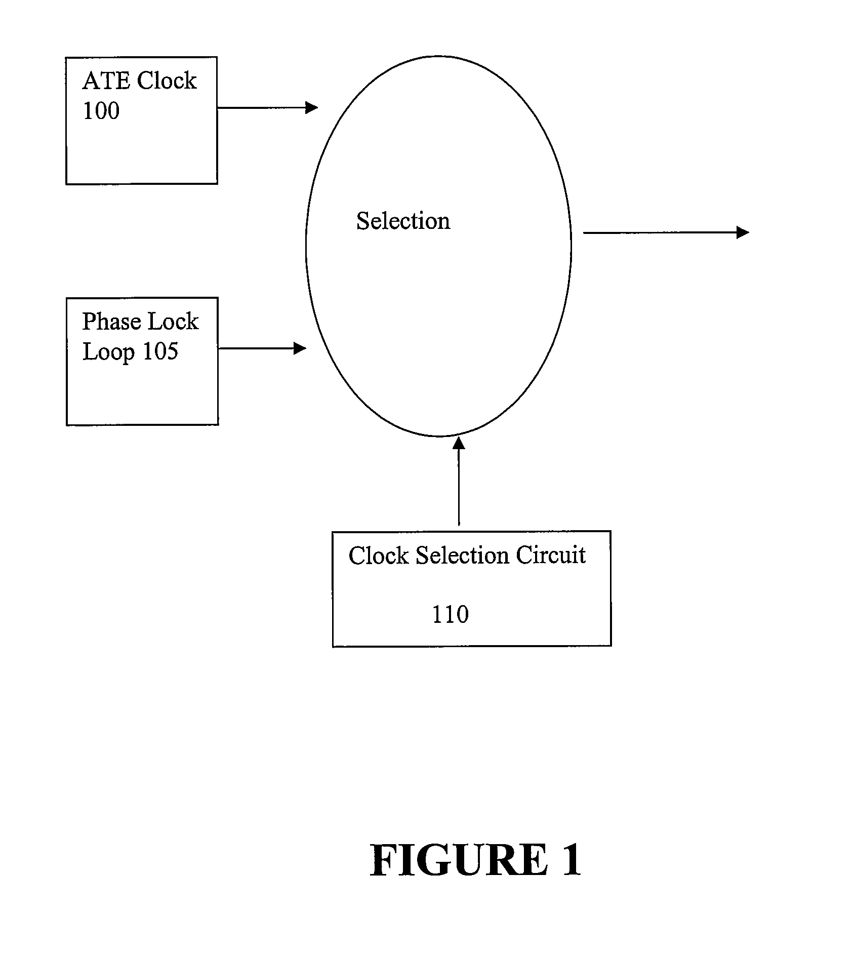
[0016]Referring now to FIG. 1, there is illustrated a block diagram for a system for scan testing in accordance with an embodiment of the present invention. The system comprises an Automatic Test Equipment (ATE) clock 100 and a phase lock loop 105. The ATE clock 100 shifts scan data to a device under test.

[0017]The ATE clock 100 shifts scan data. The phase lock loop 105 generates capture pulses. Either the ATE clock 100 signal or the capture pulses from the phase lock loop 105 are selected based on a clock select signal generated by clock select logic 110 in response to external trigger signal

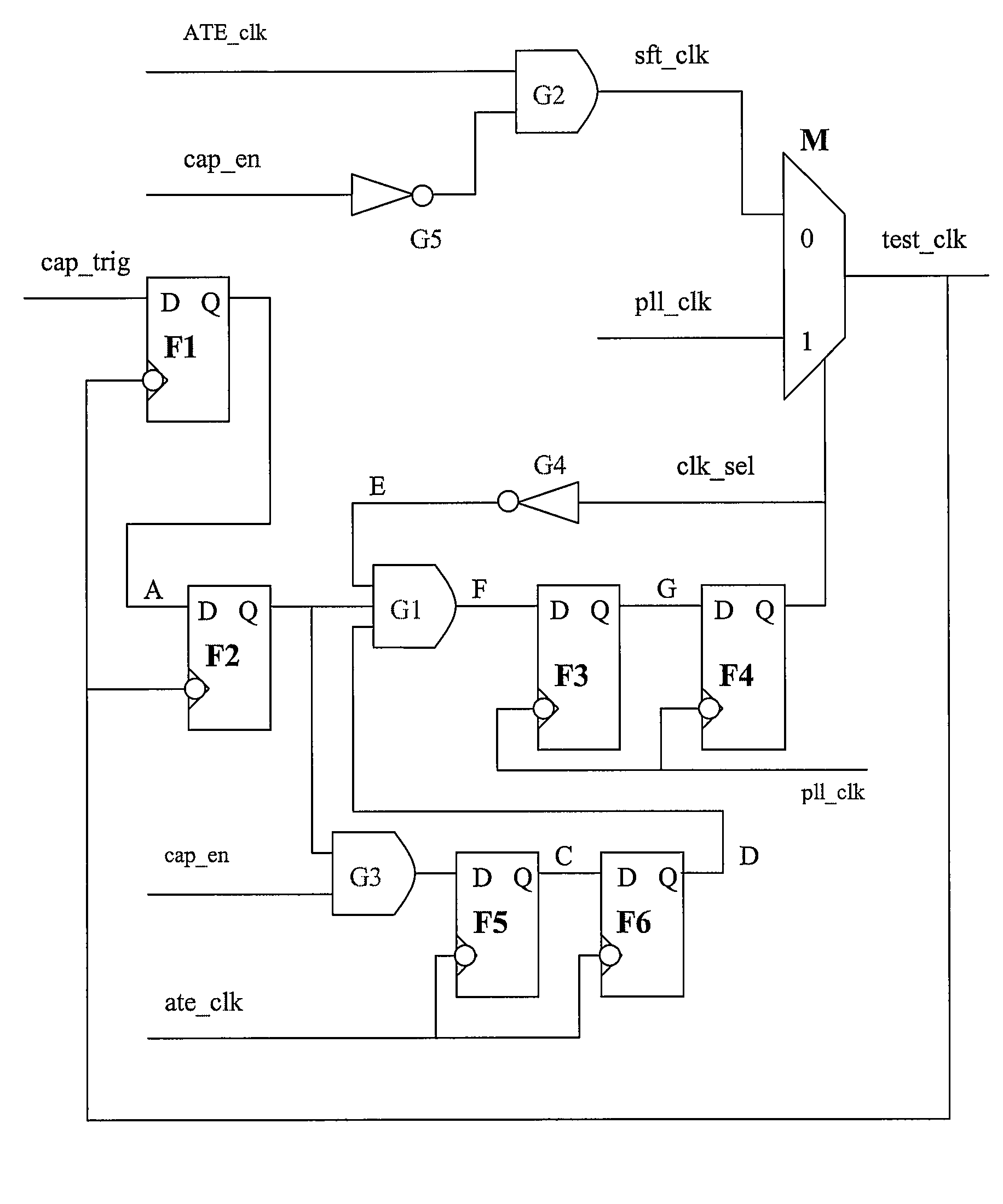
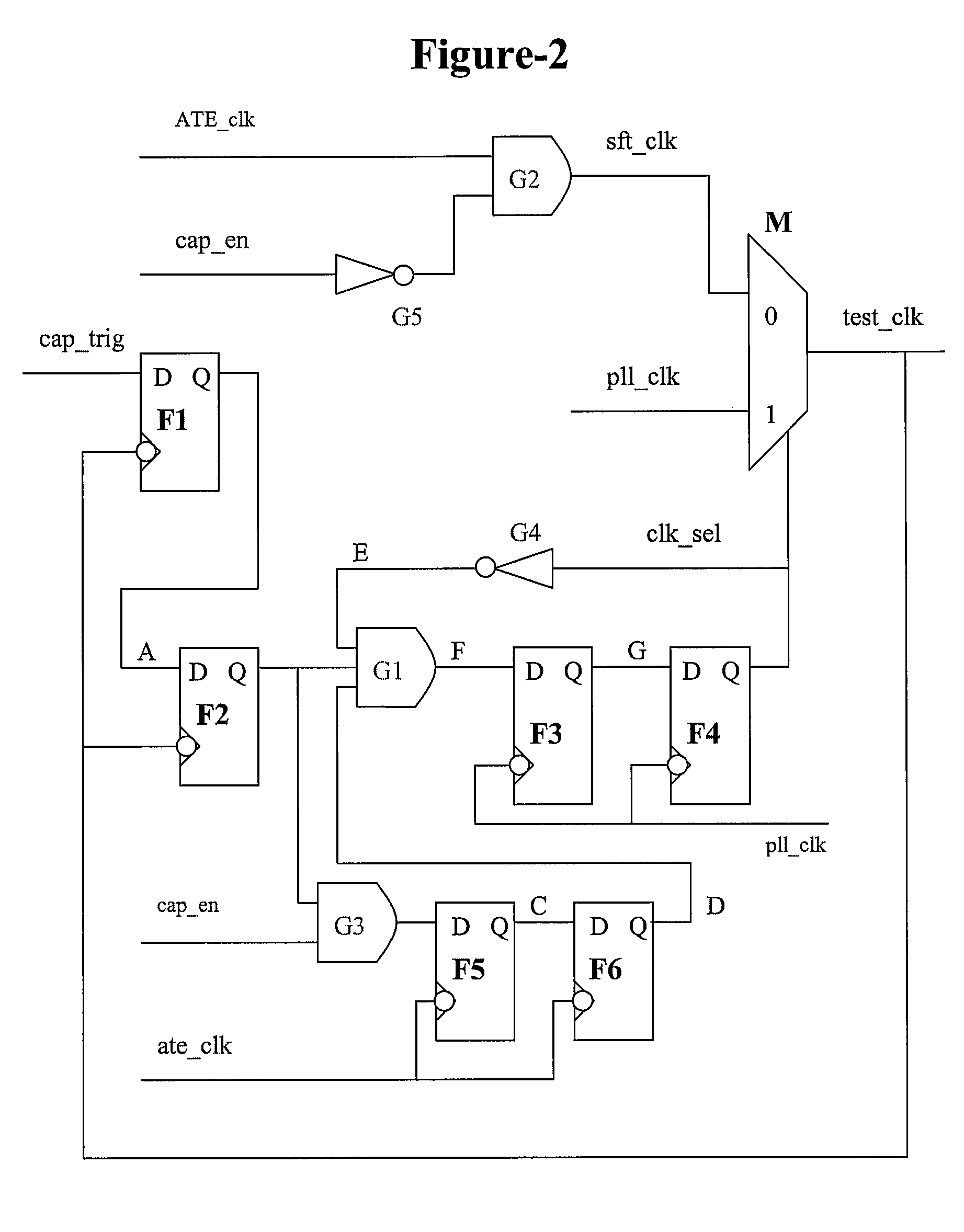
[0018]Certain embodiments can include a multiplexer for selecting between the ATE clock 100 signal and the capture pulses from the phase lock loop 105. The multiplexer can be controlled by a circuit comprising latches and flip flops that receive the external trigger signal.

[0019]Referring now to FIG. 2, there is illustrated block diagram of an integrated circuit 200 in accordance with an embodi...


PUM


Abstract

Presented herein are system(s) and method(s) for generating self-synchronized launch of last shift capture pulses using on-chip phase locked loop for at-speed scan testing. In one embodiment, there is presented a system for scan testing. The system comprises an ATE clock and a phase lock loop. The ATE clock shifts scan data. The phase lock loop generates capture pulses. The ATE clock or the capture pulses are selected based on an external synchronization signal.

Description

RELATED APPLICATIONS[0001]This application is related to patent application Ser. No. 11 / 563,493, “SYSTEM AND METHOD FOR GENERATING ON-CHIP INDIVIDUAL CLOCK DOMAIN BASED SCAN ENABLE SIGNAL USED FOR LAUNCH OF LAST SHIFT TYPE OF AT-SPEED SCAN TESTING”, by Pandey, Nov. 27, 2006, which is incorporated herein by reference for all purposes.FEDERALLY SPONSORED RESEARCH OR DEVELOPMENT[0002][Not Applicable]MICROFICHE / COPYRIGHT REFERENCE[0003][Not Applicable]BACKGROUND OF THE INVENTION[0004]In very deep sub-micron designs, integrated circuit manufacturers are starting to see more defects that are not caught by traditional stuck-at-fault testing. Defects like high impedance metal, high impedance shorts, cross talk that may not be caught by traditional stuck at scan vectors show up as timing failures that are caught by at-speed testing.[0005]Running a small number of functional vectors can be time consuming and may produce poor coverage. At speed testing can include transition delay testing and ...

Claims


Application Information

Patent Timeline
Patent Type & Authority Patents(United States)
IPC IPC(8): G01R31/3177G01R31/40
CPCG01R31/318594
Inventor PANDEY, KAMLESH
Owner AVAGO TECH INT SALES PTE LTD
Learn More