Magnetic closure

a magnetic closure and magnetic technology, applied in the field of clothing, can solve the problems of affecting the appearance, damaging the tie, and enhancing the visual appeal

Inactive Publication Date: 2011-08-09
ABADI JOSEPH
View PDF32 Cites 23 Cited by
  • Summary
  • Abstract
  • Description
  • Claims
  • Application Information

AI Technical Summary

Problems solved by technology

In addition, the traditional tie pin embellishes the visual appeal of the tie.
However, a traditional tie pin includes a pin that pierces through the tie leaving a hole each time that it is used, damaging the tie and adversely impacting its appearance.
A traditional tie clip does not damage a tie; however, it suffers from the disadvantages of being bulky, rendering the tie completely immobile at the point of attachment of the tie clip, and being less attractive in the opinion of many tie wearers.

Method used


Image

  • Magnetic closure
  • Magnetic closure
  • Magnetic closure

Examples


first embodiment

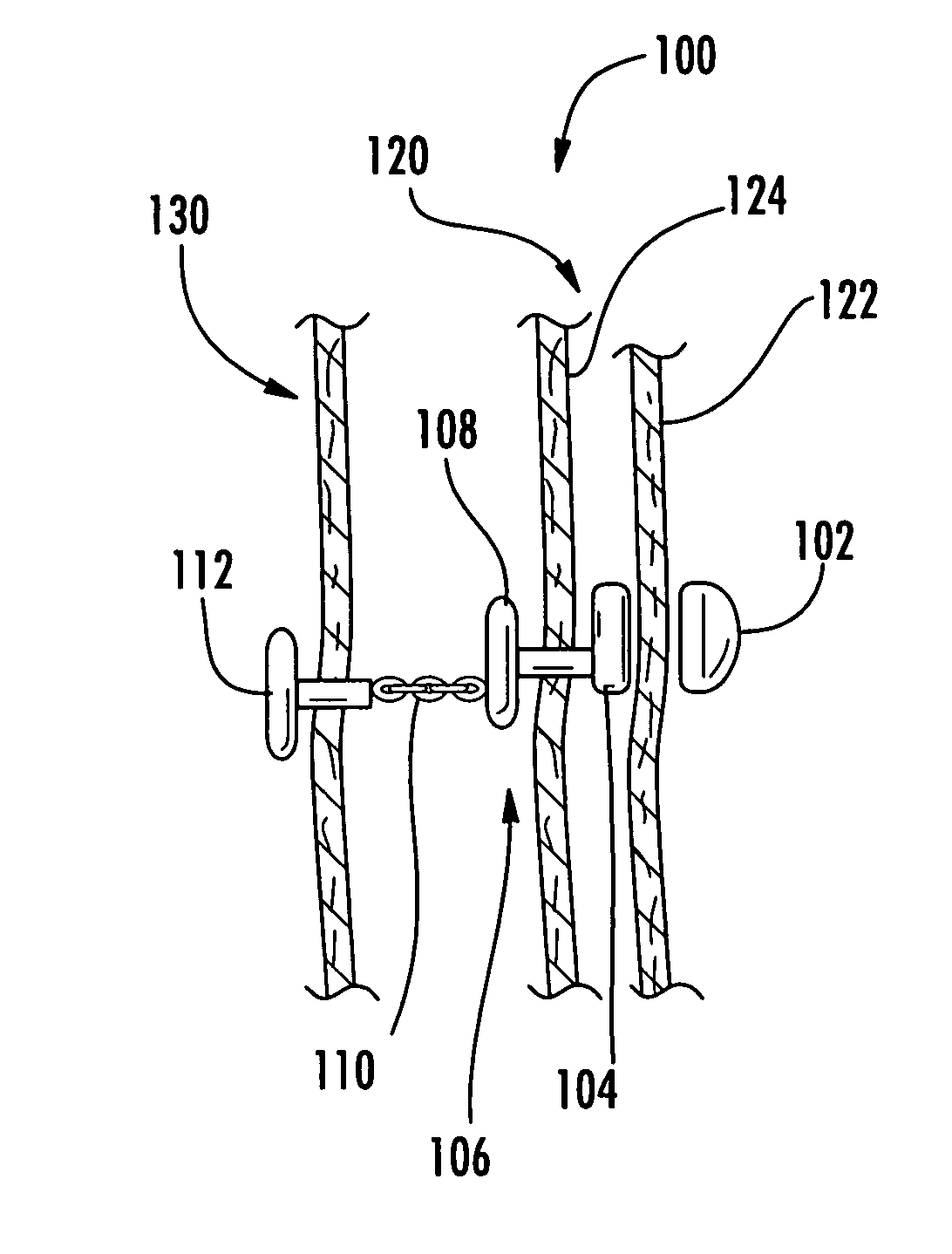
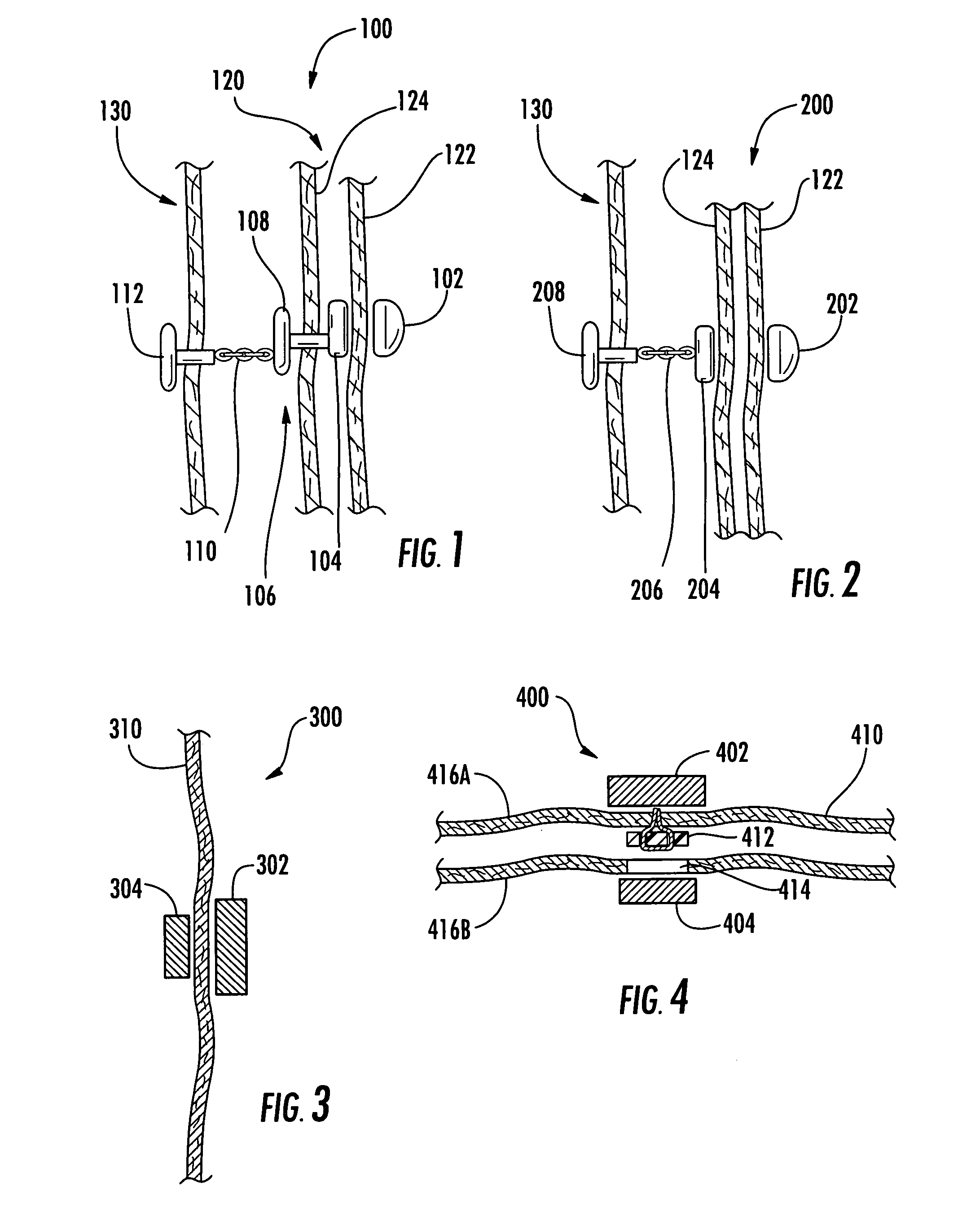
[0026]Outer magnet 202 and inner magnet 204 when coupled together hold both tie front end 122 and tie rear end 124 in place without creating any unsightly holes in tie 120. Chain 206 and T-shaped end 208 together form a connection to the wearer's shirt. Although this second preferred embodiment requires a somewhat stronger pair of inner and outer magnets in order to hold a wearer's tie as securely as the first embodiment, it offers the advantages of (1) not creating any holes whatsoever in a wearer's tie, (2) being simpler for a wearer to use (having fewer pieces or steps—there is no risk that a neophyte wearer will mistakenly pierce the front of his tie), (3) requiring less time to use when dressing in the morning, and (4) having fewer and simpler parts to manufacture, thereby reducing its cost.

[0027]In other embodiments, other components can be substituted for T-shaped end 208. For example, a second pair of magnets can be used in lieu of T-shaped end 208. The second pair of magnet...

sixth embodiment

[0032]FIG. 6 illustrates the present invention. FIG. 6 is identical in all respects to the embodiment illustrated in FIG. 1, except that chain 610 is attached to both inner magnet 104 and to outer magnet 102. Chain 610 must be sufficiently long so as to loop around tie 120 without causing tie 120 to be bent or crumpled by chain 610. Chain 610 must also be sufficiently strong so as to be able to hold outer magnet 102 (including any attached housing) without breaking, yet not be so heavy as to cause tie 120 to buckle.

[0033]Chain 610 provides the benefit that if outer magnet 102 becomes dislodged while tie pin 600 is being worn, outer magnet 102 remains attached to chain 610 and is not lost. Chain 610 also provides a different aesthetic appearance to the present invention that can be more appealing to some users.

[0034]In the embodiments illustrated in FIGS. 7 and 8, the present invention can be utilized to provide magnetic shirt buttons. A pair of magnets can function as a button, with...


PUM


Abstract

A clasp, including a first magnet, a second magnet, wherein the clasp is closed by coupling the first magnet and the second magnet and the clasp is opened by uncoupling the first magnet and the second magnet.

Description

[0001]The present application claims benefit under 35 U.S.C. §119(e)(1) to U.S. provisional application 60 / 684,371, filed May 26, 2005, the entirety of which is herein incorporated by reference.FIELD OF THE INVENTION[0002]The present invention relates to clothing.BACKGROUND[0003]A traditional tie pin prevents the tie of the wearer of the tie pin from slipping to awkward angles while allowing the tie a degree of mobility. In addition, the traditional tie pin embellishes the visual appeal of the tie. However, a traditional tie pin includes a pin that pierces through the tie leaving a hole each time that it is used, damaging the tie and adversely impacting its appearance. A traditional tie clip does not damage a tie; however, it suffers from the disadvantages of being bulky, rendering the tie completely immobile at the point of attachment of the tie clip, and being less attractive in the opinion of many tie wearers. It would therefore be desirable to provide a tie pin that did not dama...

Claims


Application Information

Patent Timeline
Patent Type & Authority Patents(United States)
IPC IPC(8): A44B99/00A41D25/00A44B1/04
CPCA41F1/002A44B5/00A44B9/08Y10T24/19Y10T24/1397Y10T24/32
Inventor ABADI, JOSEPH
Owner ABADI JOSEPH
Why Eureka
Try Eureka