Systems and methods for interventional medicine

a technology of interventional medicine and system, applied in the field of interventional medicine systems, can solve the problems of not providing adequate manipulation of the distal tip of the medical device for conducting preventing the use of deterministic equations to guide the device, and not providing adequate manipulation of the distal tip of the medical device for many diagnostic and therapeutic procedures. , to achieve the effect of reducing exposure to x-rays or high magnetic fields

Inactive Publication Date: 2005-11-17
STEREOTAXIS
View PDF11 Cites 397 Cited by
  • Summary
  • Abstract
  • Description
  • Claims
  • Application Information

AI Technical Summary

Benefits of technology

[0007] The present system and method provide clear and unambiguous images of the tissues in the operating region, including an image or accurate representation of the catheter device. The present system and method can also provide the capability for operation from a remote location, removing the physician from the procedure site and thereby reducing exposure to X-rays or high magnetic fields from imaging devices. Remote operation also allows a particularly skilled physicians to operate over a broader geographical area.

Problems solved by technology

However, currently available interventional medicine systems do not provide adequate manipulation of the distal tip of a medical device for conducting many diagnostic and therapeutic procedures.
If the device has made significant bends along the path from the entrance site to the treatment site, torque may not be transmitted in a predictable manner from the physician's hands to the device tip.
The pull wires tend to make the distal end of the device stiff, and they occupy valuable space in the small cross sectional area of the device, which must often contain other devices for diagnosis or treatment.
The lack of a predictable response of the catheter distal tip to movements at the proximal end, prevents the use of deterministic equations to guide the device.

Method used


Image

  • Systems and methods for interventional medicine
  • Systems and methods for interventional medicine
  • Systems and methods for interventional medicine

Examples


Embodiment Construction

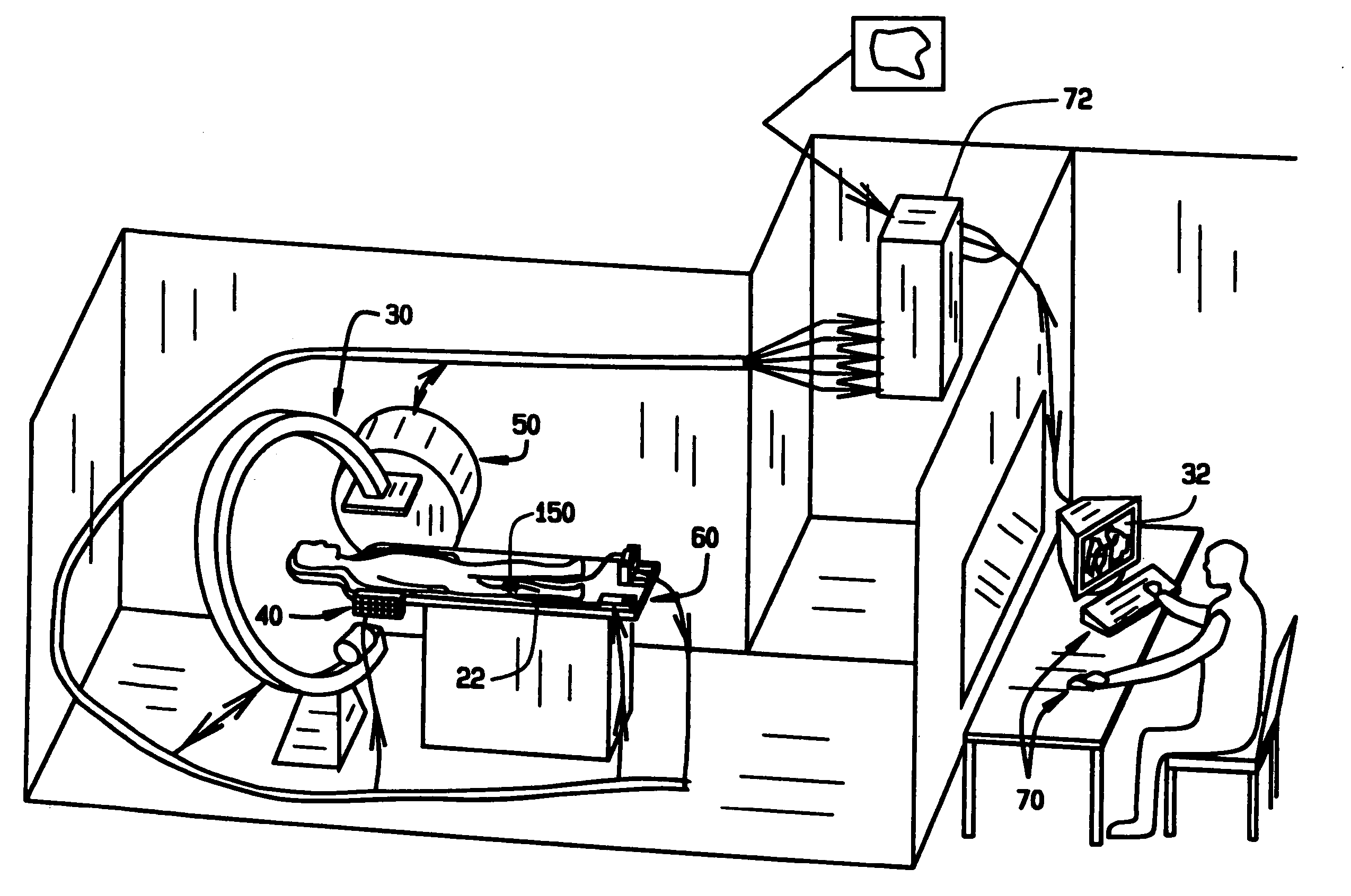
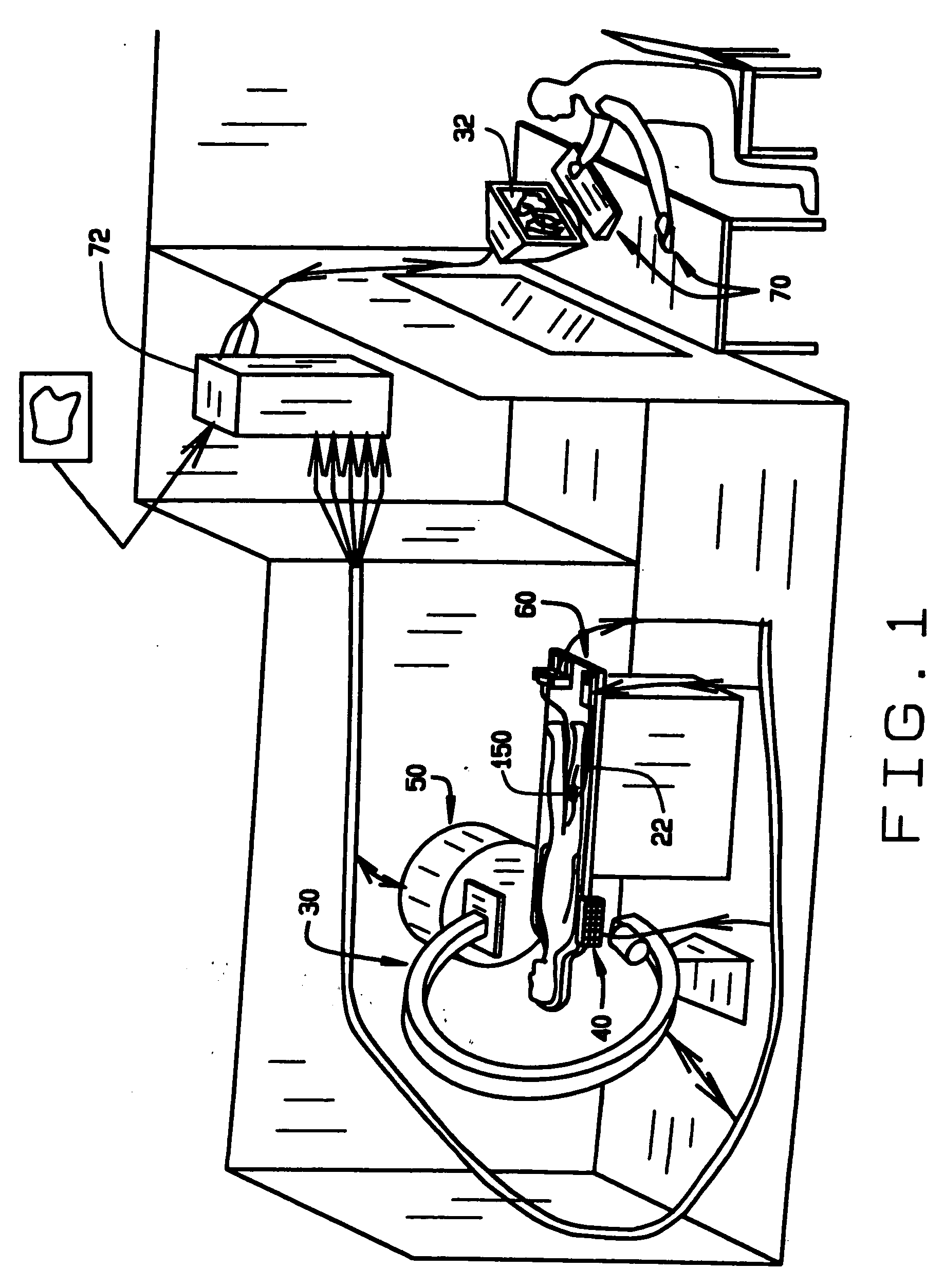
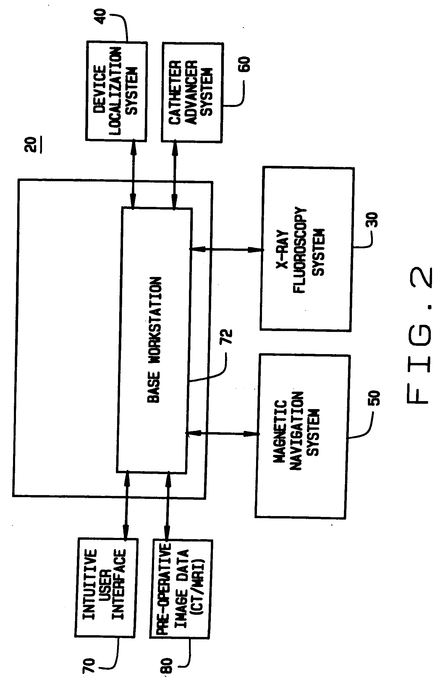
[0028] An automated system for navigating a medical device through the lumens and cavities in an operating region in a patient in accordance with the principles of this invention is indicated generally as 20 in FIG. 1. The system 20 comprises an elongate medical device 22, having a proximal end 24 and a distal end 26 adapted to be introduced into the operating region O in a patient P. The system 20 also comprises an imaging system 30 for displaying an image of the operating region O on a display 32, including a representation of the distal end 26 of the medical device 22 in the operating region O.

[0029] The system 20 also includes a localization system 40 for determining the position of the medical device 22 in a frame of reference translatable to the displayed image of the imaging system.

[0030] The system 20 also includes a navigation system for manipulating the distal end 26 of the medical device 22. In this preferred embodiment the navigating system is a magnetic navigation sys...


PUM


Abstract

An automated system for navigating a medical device through the lumens and cavities in an operating region in a patient. The system includes an elongate medical device, having a proximal end and a distal end adapted to be introduced into the operating region. The system also includes an imaging system for displaying an image of the operating region, including a representation of the distal end of the medical device in the operating region. The system also includes a localization system for determining the position of the medical device in a frame of reference translatable to the displayed image of the imaging system. Finally, the system includes a system for orienting the medical device in a selected direction in the operating region, this system may be, for example, a magnetic navigation system which acts through the interaction of magnetic fields associated with the medical device inside the operating region and at least one external source magnet outside the patient's body.

Description

CROSS REFERENCE TO RELATED APPLICATION [0001] This application claims priority of prior PCT Application Serial No. PCT / US03 / 10893, filed Apr. 9, 2003, which claimed priority of Provisional U.S. Application Ser. No. 60 / 371,555, filed Apr. 10, 2002, the entire disclosures of which are incorporated herein by reference.FIELD OF THE INVENTION [0002] This invention relates to a system and methods for interventional medicine. BACKGROUND OF THE INVENTION [0003] Interventional medicine is the collection of medical procedures in which access to the site of treatment is made through one of the patient's blood vessels, body cavities or lumens. For example, angioplasty of a coronary artery is most often performed using a catheter which enters the patient's arterial system through a puncture of the femoral artery in the groin area. The procedure is referred to as PTCA, or Percutaneous (through the skin), Transluminal (through the blood vessel), Coronary (in the vessel of the heart), Angioplasty. ...

Claims


Application Information

Patent Timeline
Patent Type & Authority Applications(United States)
IPC IPC(8): A61B5/05A61B19/00
CPCA61B19/22A61B2019/2265A61B2019/2253A61B19/52A61B90/36A61B34/70A61B34/73A61B2034/733
Inventor HASTINGS, ROGER N.RITERS, ROGERS C.WERP, PETER R.HALL, ANDREW F.BLUME, WALTER M.RAUCH, JOHNKLIMEK, SCOTT G.VISWANATHAN, RAJU R.
Owner STEREOTAXIS
Why Eureka
Try Eureka