Magnetic-flap optical sensor

a technology of optical sensors and magnetic fields, applied in the field of magnetic fields, can solve problems such as errors in conventional pulse oximetry

Active Publication Date: 2017-08-01
MASIMO CORP
View PDF715 Cites 357 Cited by
  • Summary
  • Abstract
  • Description
  • Claims
  • Application Information

AI Technical Summary

Benefits of technology

[0007]A magnetic-flap optical sensor is configured to attach to a tissue site so as to illuminate the tissue site with optical radiation and detect the optical radiation after attenuation by pulsatile blood flow within the tissue site. The sensor communicates with a physiological monitor so as to calculate parameters corresponding to constituents of the pulsatile blood flow. The sensor has top and bottom finger clip shells connected by a pivot pin and urged together by a spring. The shells retain pads that receive an inserted fingertip and position this tissue site with respect to emitters and detector(s) so as to allow the sensor processor to activate the emitters and receive a corresponding signal from the detector(s) indicative of a physiological characteristic of the tissue site. The emitters and detector(s) are retained between the shell and the pads. An active pulser is retained between the shell and the lower pad. Magnetic flaps extend from an upper one of the pads and are urged against the bottom shell, advantageously occluding blood flow out of the inserted fingertip and accentuating the active pulse induced signal accordingly.

Problems solved by technology

During patient motion, venous blood also moves, which causes errors in conventional pulse oximetry.

Method used


Image

  • Magnetic-flap optical sensor
  • Magnetic-flap optical sensor
  • Magnetic-flap optical sensor

Examples


Embodiment Construction

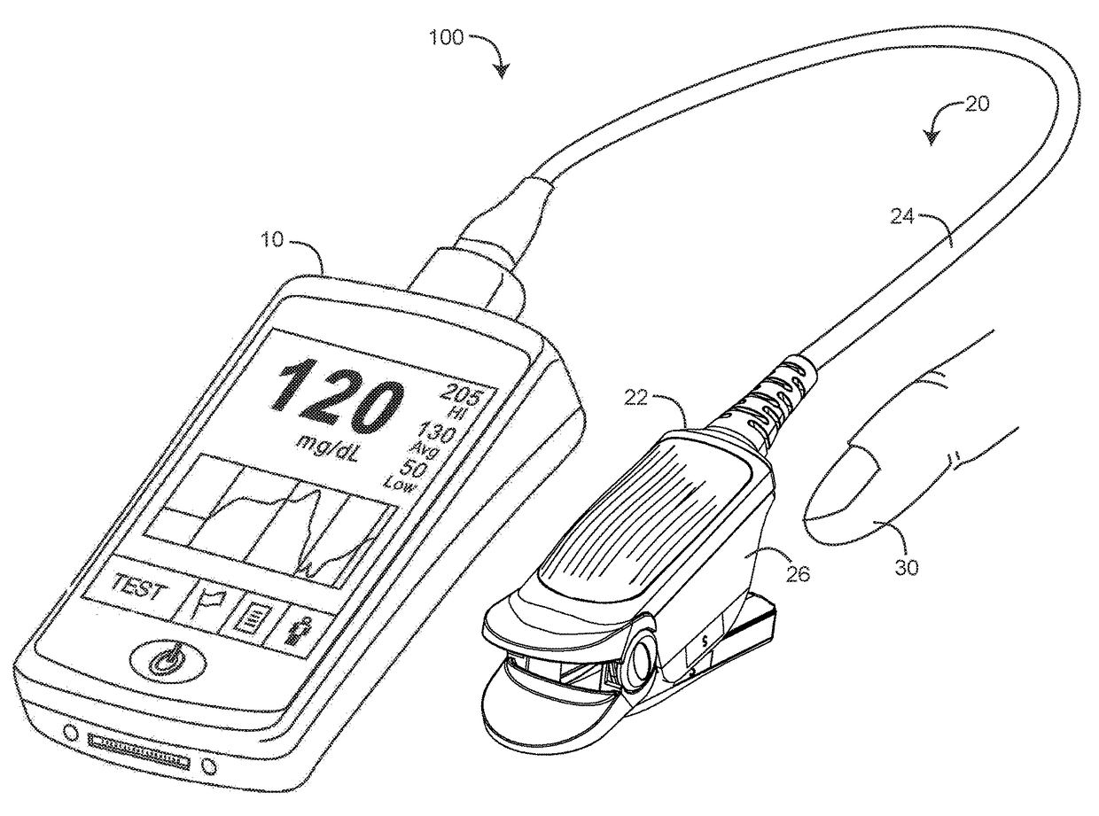
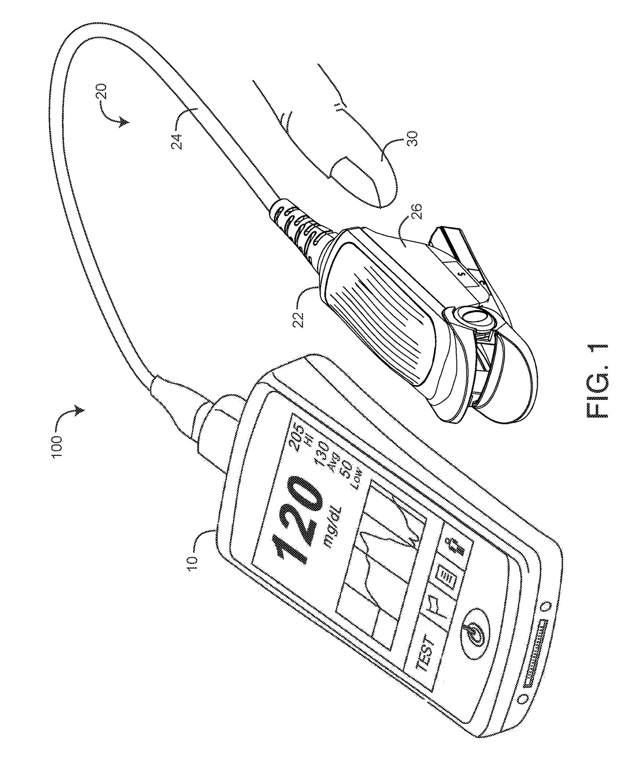
[0019]FIG. 1 illustrates a noninvasive physiological monitoring assembly 100 having a magnetic flap optical sensor 20 in communications with a multi-parameter monitor 10. The magnetic flap optical sensor 20 is configured to illuminate a fingertip 30 with multiple wavelength optical radiation and detect the optical radiation after attenuation by pulsatile blood flow within the fingertip 30. In an embodiment, the sensor 20 has a reusable finger clip 22 that removably and reusably attaches to the fingertip 30 and a sensor cable 24 that communicates with the monitor 10. Advantageously, the finger clip 22 has magnetic flaps 26 that occlude blood flow within the fingertip 30 so as to accentuate pulsatile blood flow in response to an mechanically-generated “active” pulse. In particular, the magnetic flaps 26 capture a higher blood volume within the fingertip 30 resulting in a larger pulsatile optical signal in response to the active pulse. Magnetic flap fingertip occlusion is described in ...


PUM


Abstract

A magnetic-flap optical sensor has an emitter activated so as to transmit light into a fingertip inserted between an emitter pad and a detector pad. The sensor has a detector responsive to the transmitted light after attenuation by pulsatile blood flow within fingertip so as to generate a detector signal. Flaps extend from the emitter pad and along the sides of a detector shell housing the detector pad. Flap magnets are disposed on the flap ends and shell magnets are disposed on the detector shell sides. A spring urges the emitter shell and detector shell together, so as to squeeze the fingertip between its fingernail and its finger pad. The flap magnets have opposite north and south orientations from the shell magnets, urging the flaps to the detector shell sides and squeezing the fingertip sides. These spring and magnet squeezing forces occlude the fingertip blood flow and accentuate a detector signal responsive to an active pulsing of the fingertip.

Description

PRIORITY CLAIM AND REFERENCE TO RELATED APPLICATIONS[0001]The present application claims priority benefit under 35 U.S.C. §119(e) to U.S. Provisional Patent Application Ser. No. 61 / 716,486, filed Oct. 20, 2012, titled Magnetic-Flap Optical Sensor, hereby incorporated in its entirety by reference herein.BACKGROUND OF THE INVENTION[0002]Noninvasive physiological monitoring systems for measuring constituents of circulating blood have advanced from basic pulse oximeters to monitors capable of measuring abnormal and total hemoglobin among other parameters. A basic pulse oximeter capable of measuring blood oxygen saturation typically includes an optical sensor, a monitor for processing sensor signals and displaying results and a cable electrically interconnecting the sensor and the monitor. A pulse oximetry sensor typically has a red wavelength light emitting diode (LED), an infrared (IR) wavelength LED and a photodiode detector. The LEDs and detector are attached to a patient tissue site...

Claims


Application Information

Patent Timeline
Patent Type & Authority Patents(United States)
IPC IPC(8): A61B5/00A61B5/024A61B5/1455
CPCA61B5/6838A61B5/02422A61B5/14551A61B5/6826A61B2562/0238
Inventor LAMEGO, MARCELO M.VO, HUNGDALVI, CRISTIANOMERRITT, SEAN
Owner MASIMO CORP
Why Eureka
Try Eureka