Structure of staple magazine having permanent magnet

a technology of staple magazines and permanent magnets, which is applied in the field of staple magazines, can solve the problems of increased weight of staplers, inconvenient use of staplers, and excessive load on the fingers of users

Inactive Publication Date: 2008-06-26
UHM HYUN DUK
View PDF6 Cites 406 Cited by
  • Summary
  • Abstract
  • Description
  • Claims
  • Application Information

AI Technical Summary

Benefits of technology

[0005]In order to accomplish the above object, the present invention provides a structure of a staple magazine for a stapler, including a base having on a front end thereof an anvil for bending a staple, a lower surface of the base being covered with a cover, a support provided on a rear end of the base, the support having opposite sidewalls, the staple magazine coupled at a rear end thereof to inner surfaces of the sidewalls of the support so as to be rotatable, the staple magazine containing a staple cartridge therein, and a handle for covering an upper part of the staple magazine, the handle being rotatably coupled at a rear end thereof to the sidewalls of the support, with a punching blade provided in the handle, wherein a front permanent magnet is provided on the front wall of the staple magazine, which contains the staple cartridge therein, at a predetermined position adjacent to an ejection slot formed in the staple magazine, so that the staple cartridge is attracted towards the ejection slot of the staple magazine by the magnetic attraction force of the front permanent magnet, and, when the handle is pushed, the frontmost staple of the staple cartridge, which is aligned with the ejection slot, is ejected by the punching blade of the handle to staple paper sheets, and the space where the frontmost staple was is filled with the staple cartridge, which is automatically attracted towards the ejection slot of the staple magazine by the magnetic attraction force of the front permanent magnet, thus making it possible to continuously conduct the stapling operation.

Problems solved by technology

At this time, an excessive load may be applied to the finger of a user.
As such, the conventional stapler has a structural disadvantage in that the use thereof is inconvenient to the user.
Furthermore, there are disadvantages in that, because the spring structure of the staple magazine 60 includes the spring 2, the spring guide rod 4, the tension lever and the guide block 6, the weight of the stapler is increased, and the structure of the stapler is complicated, so that the process of manufacturing the stapler is also complicated.

Method used


Image

  • Structure of staple magazine having permanent magnet
  • Structure of staple magazine having permanent magnet
  • Structure of staple magazine having permanent magnet

Examples


Embodiment Construction

[0011]Hereinafter, preferred embodiments of the present invention will be described in detail with reference to the attached drawings.

[0012]The terms and words used in the specification and claims must not be limited to typical or dictionary meanings, but must be regarded as concepts selected by the inventor as the best method of illustrating the present invention, and must be interpreted as having meanings and concepts adapted to the scope and spirit of the present invention for understanding the technology of the present invention.

[0013]Therefore, the construction of the embodiments illustrated in the specification and the drawings must be regarded as only illustrative examples, which are not intended to limit the present invention. Furthermore, it must be understood that various modifications, additions, and substitutions are possible at the point of time of application of the present invention.

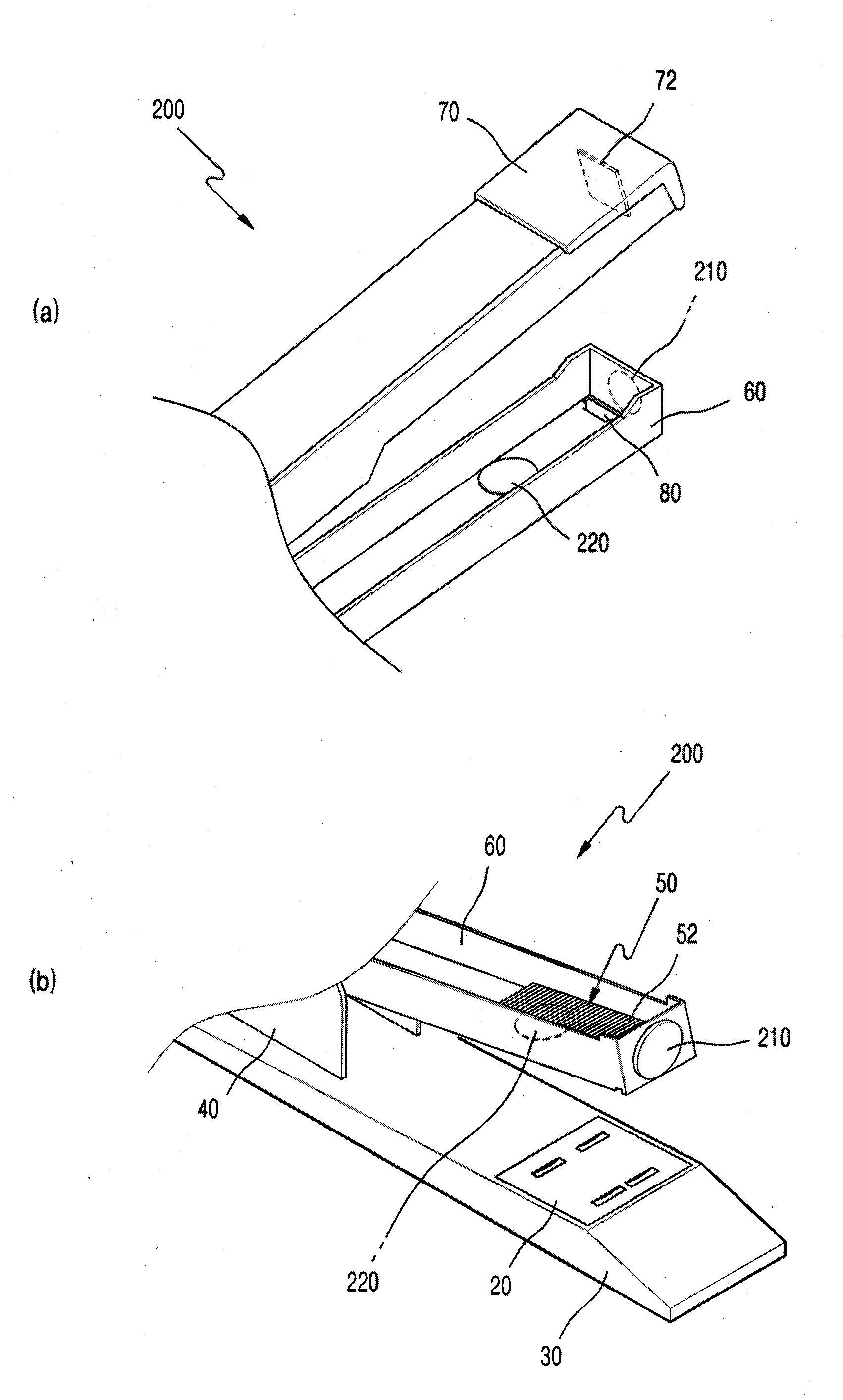
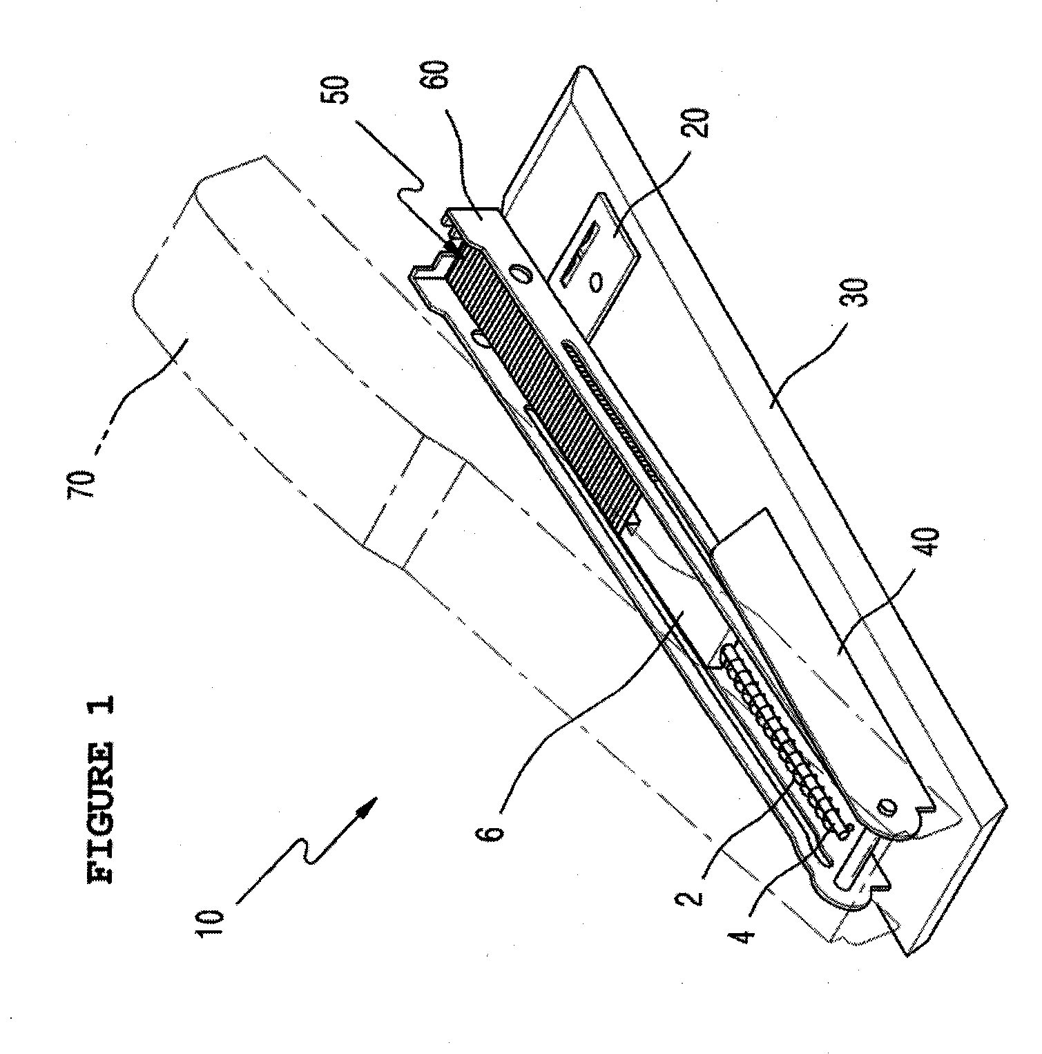
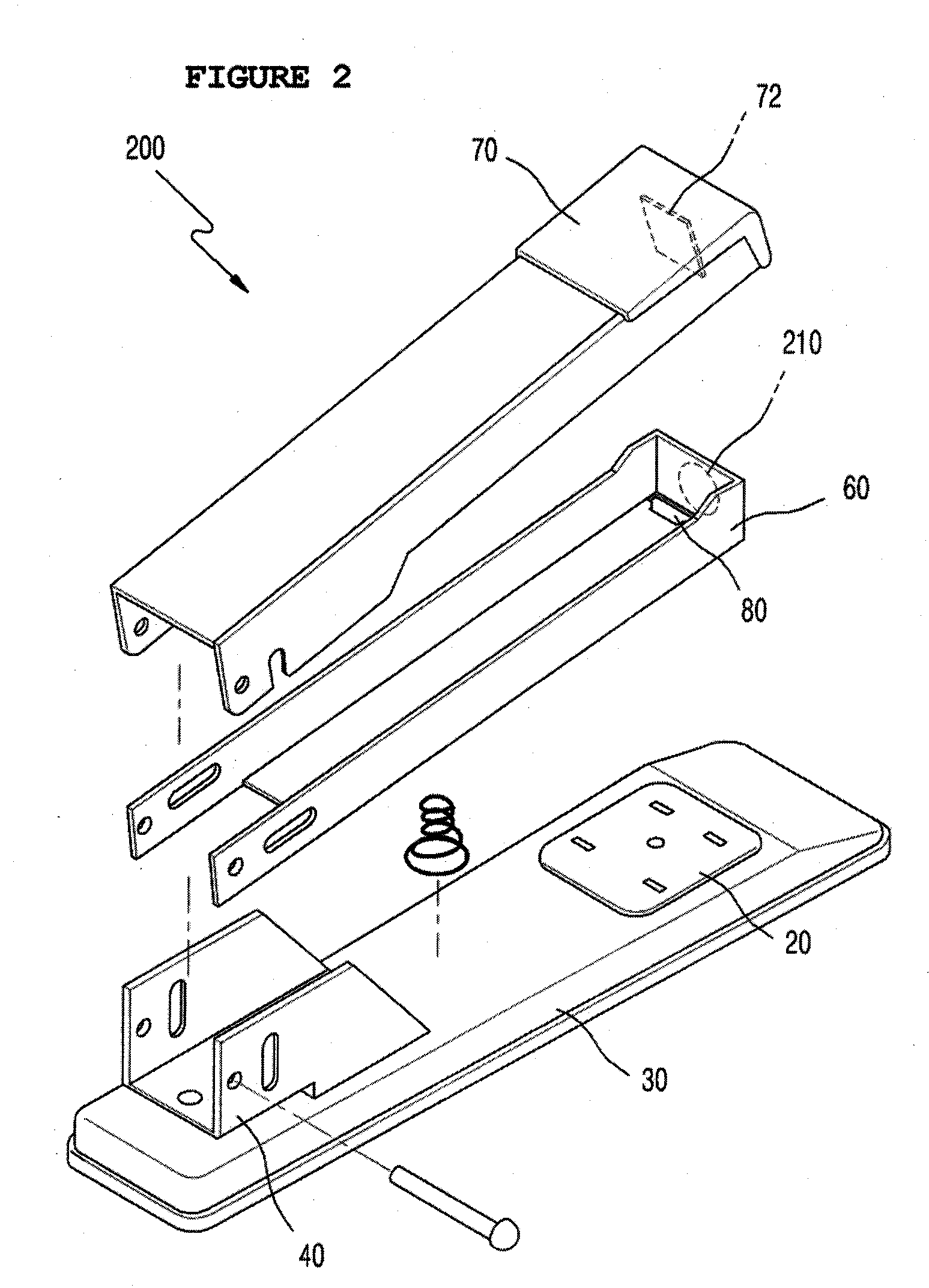
[0014]FIG. 2 is an exploded perspective view of a stapler provided with a staple magaz...


PUM


Abstract

The present invention uses the principle in which staples made of iron are attracted in a direction in which magnetic attraction force is generated. Using this principle, a permanent magnet is provided on a front wall of a staple magazine, so that a staple cartridge is attracted towards an ejection slot of the staple magazine by the magnetic attraction force of the permanent magnet. When a handle having a punching blade is pushed, the frontmost staple in the staple cartridge, which is aligned with the ejection slot, is ejected by the punching blade to staple paper sheets. After the frontmost staple is ejected, the staple cartridge is automatically moved to and brought into close contact with the front wall of the staple magazine such that a subsequent staple, which is in a frontmost position, is aligned with the ejection slot to prepare for a subsequent stapling operation.

Description

FIELD OF THE INVENTION[0001]The present invention relates generally to staple magazines for staplers and, more particularly, to a structure of a staple magazine for staplers in which a permanent magnet is provided on the front end of the staple magazine, so that, using the principle in which staples, that is, a staple cartridge, made of iron, are attracted in the direction from which magnetic attraction force is generated, the permanent magnet conducts the same function as that of a spring structure of a conventional stapler, in which a staple cartridge contained in the staple magazine is pushed by the restoring force of the spring.DESCRIPTION OF THE RELATED ART[0002]Generally, as shown in FIG. 1, a conventional stapler 10 includes a spring structure, which includes a spring 2, a spring guide rod 4, a tension lever and a guide block 6 for pushing a staple cartridge 50 contained in a staple magazine 60. To staple paper sheets, a frontmost staple 52 of the staple cartridge is ejected ...

Claims


Application Information

Patent Timeline
Patent Type & Authority Applications(United States)
IPC IPC(8): B25C5/16
CPCB25C5/1606
Inventor UHM, HYUN DUK
Owner UHM HYUN DUK
Why Eureka
Try Eureka