
Pressure sensor

a pressure sensor and sensor technology, applied in the field of pressure sensors, can solve the problems of pressure sensor size increase, size and weight increase correspondingly,

Inactive Publication Date: 2011-08-09
MATSUSHITA ELECTRIC WORKS LTD
View PDF32 Cites 15 Cited by
  • Summary
  • Abstract
  • Description
  • Claims
  • Application Information

AI Technical Summary

Benefits of technology

"The present invention relates to a pressure sensor with a pressure detecting element located close to a through hole in the body portion. The body portion is made of a molded interconnect device with a conductive pattern formed on its surface. The pressure detecting element can be mounted on the body portion using flip-chip bonding. The pressure sensor can have a recess with a bottom face and a step face, and the pressure detecting element and another element can be mounted on the bottom face and the step face, respectively. The recess can be vacuum sealed. The pressure sensor can be made of an elastic material and formed using a molded interconnect device technique. The pressure detector can detect pressure variation as capacitance variation between electrode patterns formed on its surface. The body portion can include a pressure introducing tube with a projection for sealing a gap between the inner surface of the detection tube and the outer surface of the pressure introducing tube. The pressure sensor can also include a signal processing circuit that processes the electric signal received from the pressure detector. The pressure detector can include a dielectric film and an electrode formed on the dielectric film. The body portion can include a fitting portion that is cylindrical in shape and fitted to a tube in which fluid is present."

Problems solved by technology

However, the conventional pressure sensor has a problem that because it includes the glass pedestal, the size and weight are increased correspondingly.
Because the sensor chip mounted by wire bonding, there are problems that the mounting operation becomes complicated, and it becomes necessary to form a space for carrying out the wire bonding, so that the pressure sensor is increased in size.

Method used


Image

  • Pressure sensor
  • Pressure sensor
  • Pressure sensor

Examples


first embodiment

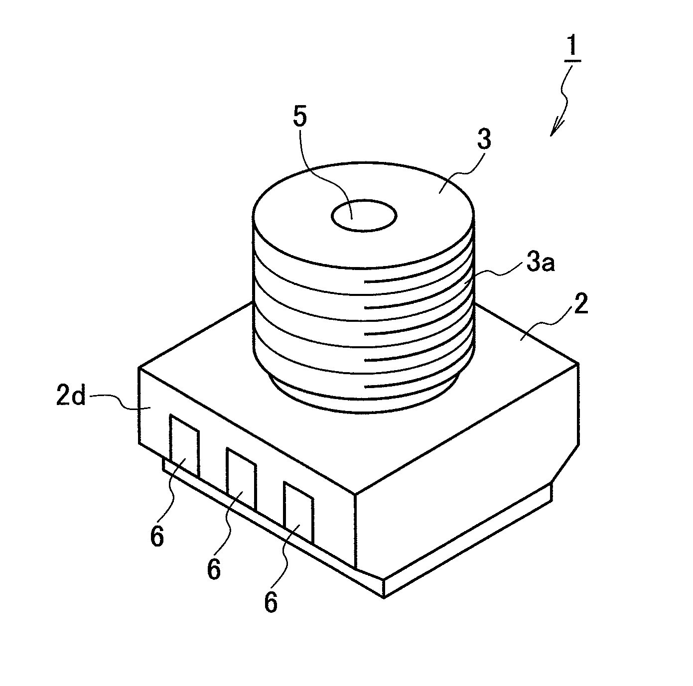
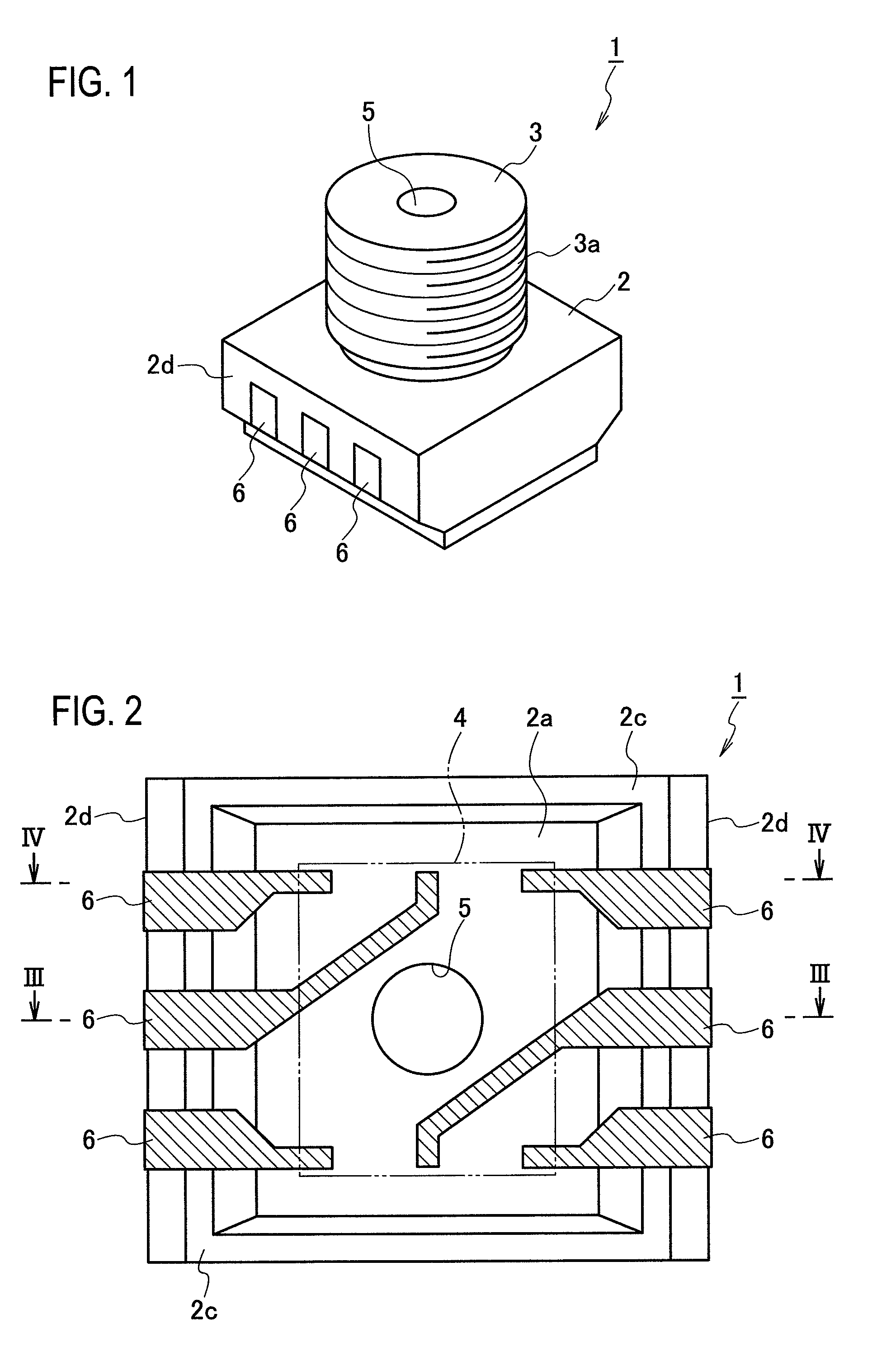
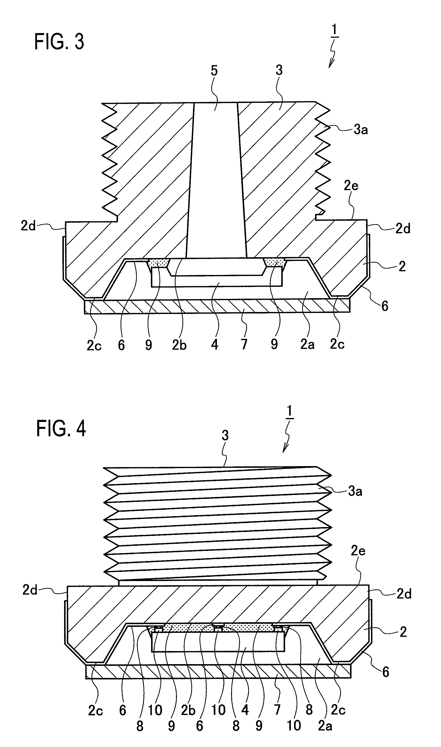
[0042]FIG. 1 is a perspective view of a pressure sensor according to a first embodiment of the present invention, FIG. 2 is a plan view of a pressure sensor as viewed from its back side (opposite side from a detection side by a pressure detecting element), FIG. 3 is a sectional view taken along the line III-III in FIG. 2, FIG. 4 is a sectional view taken along the line IV-IV in FIG. 2, FIG. 5 is a plan view of the pressure sensor as viewed from its back side and showing a sealing region of the pressure detecting element by a sealing agent, and FIG. 6 is a side view showing a state where the pressure sensor is mounted.

[0043]A pressure sensor 1 according to the present embodiment includes a substantially-cylindrical protrusion 3 provided on a flat surface (seal surface) 2e of a base portion 2 having a substantially rectangular parallelepiped appearance. In the present embodiment, the base portion 2 and the protrusion 3 correspond to a body portion.

[0044]The body portion (the base port...

second embodiment

[0062]FIG. 7 is a vertical sectional view of a pressure sensor according to a second embodiment of the present invention (corresponding to the sectional view of FIG. 3). A pressure sensor 1A according to the present embodiment includes same constituent elements as those of the pressure sensor 1 according to the first embodiment. Therefore, same constituent elements are denoted by common reference numerals, and redundant explanations thereof will be omitted.

[0063]In the present embodiment, a stepped recess 2a having the bottom face 2b and a step face 2f formed substantially at a central portion in a depth direction of a stepped recess 2a is formed on the base portion 2A. The pressure detecting element 4 is mounted on the bottom face 2b, and another element that is different from the pressure detecting element 4 (i.e., an element including a circuit that processes (i.e., filters, corrects, calculates, temperature compensates) a signal output from the pressure detecting element 4) is m...

third embodiment

[0068]FIG. 8 is a vertical sectional view of a pressure sensor according to a third embodiment of the present invention (sectional view corresponding to FIG. 3). A pressure sensor 1B according to the present embodiment has same constituent elements as those of the pressure sensor 1 or 1A of the first or second embodiment. Therefore, the same constituent elements are denoted by common reference numerals, and redundant explanations thereof will be omitted.

[0069]In the present embodiment, an annular flange portion 13 protruding from an inner peripheral surface of the through hole 5 of a base portion 2B toward a center of the through hole 5 is formed. The pressure detecting element 4 is mounted on a surface 5a of the flange portion 13 on the side of a pressure introducing opening 5b of the through hole 5 by flip-chip bonding. Another element 4B that is different from the pressure detecting element 4 (i.e., an element including a circuit that processes (i.e., filters, corrects, calculate...


PUM

PropertyMeasurementUnit
temperatureaaaaaaaaaa

Abstract

In a pressure sensor including a pressure detecting element in an intermediate portion or at a deep side of a through hole formed in a protrusion, a body portion (a base portion and the protrusion) is made of ceramic or an insulative resin material and molded into a predetermined shape, and the pressure sensor is constituted as a molded interconnect device in which a conductive pattern is formed on a surface thereof. Accordingly, a smaller pressure sensor can be obtained.

Description

TECHNICAL FIELD[0001]The present invention relates to a pressure sensor that detects a pressure of fluid.BACKGROUND ART[0002]There is conventionally known a pressure sensor having a sensor chip that closes one end of a through hole as a pressure introducing hole formed in a package body (for example, Patent Document 1).[0003]According to a pressure sensor disclosed in Patent Document 1, a sensor chip is mounted on a resin package body through a glass pedestal by wire bonding. To secure desired detection accuracy, the glass pedestal has a function for reinforcing the package body to secure the desired detection accuracy of the sensor chip.[0004]However, the conventional pressure sensor has a problem that because it includes the glass pedestal, the size and weight are increased correspondingly.[0005]Because the sensor chip mounted by wire bonding, there are problems that the mounting operation becomes complicated, and it becomes necessary to form a space for carrying out the wire bond...

Claims


Application Information

Patent Timeline
Patent Type & Authority Patents(United States)
IPC IPC(8): G01L9/12
CPCG01L9/0075G01L9/00G01L19/14H01L29/24
Inventor KOBAYASHI, MITSURUINOUE, HIROSHIMAKINAGA, HITOSHIIMAI, JUNJIMASAKI, YASUFUMIIKEGAWA, NAOTONAKAHARA, YOUICHIRO
Owner MATSUSHITA ELECTRIC WORKS LTD
Learn More