
Variable rate diverter for a crop residue collecting device carried by a combine harvester

a technology of crop residue and diverter, which is applied in the field of collecting crop residue discharged from a combine harvester, can solve problems such as unsatisfactory operation, and achieve the effect of improving the flow splitting arrangement of crop residu

Inactive Publication Date: 2011-08-09
DEERE & CO
View PDF21 Cites 46 Cited by
  • Summary
  • Abstract
  • Description
  • Claims
  • Application Information

AI Technical Summary

Benefits of technology

Enables seamless switching between extreme and intermediate modes, preventing plugging and allowing precise control over the distribution of crop residue between collection and spreading, enhancing operational efficiency.

Problems solved by technology

While this usage of a wedge-shaped nose for splitting the residue flow worked satisfactorily in respective modes wherein all of the flow was collected or all of the flow was diverted, the operation was not satisfactory for varying the flow between these two extreme modes, and crop residue tended to hairpin on the splitting nose resulting in plugging.

Method used


Image

  • Variable rate diverter for a crop residue collecting device carried by a combine harvester
  • Variable rate diverter for a crop residue collecting device carried by a combine harvester
  • Variable rate diverter for a crop residue collecting device carried by a combine harvester

Examples


Embodiment Construction

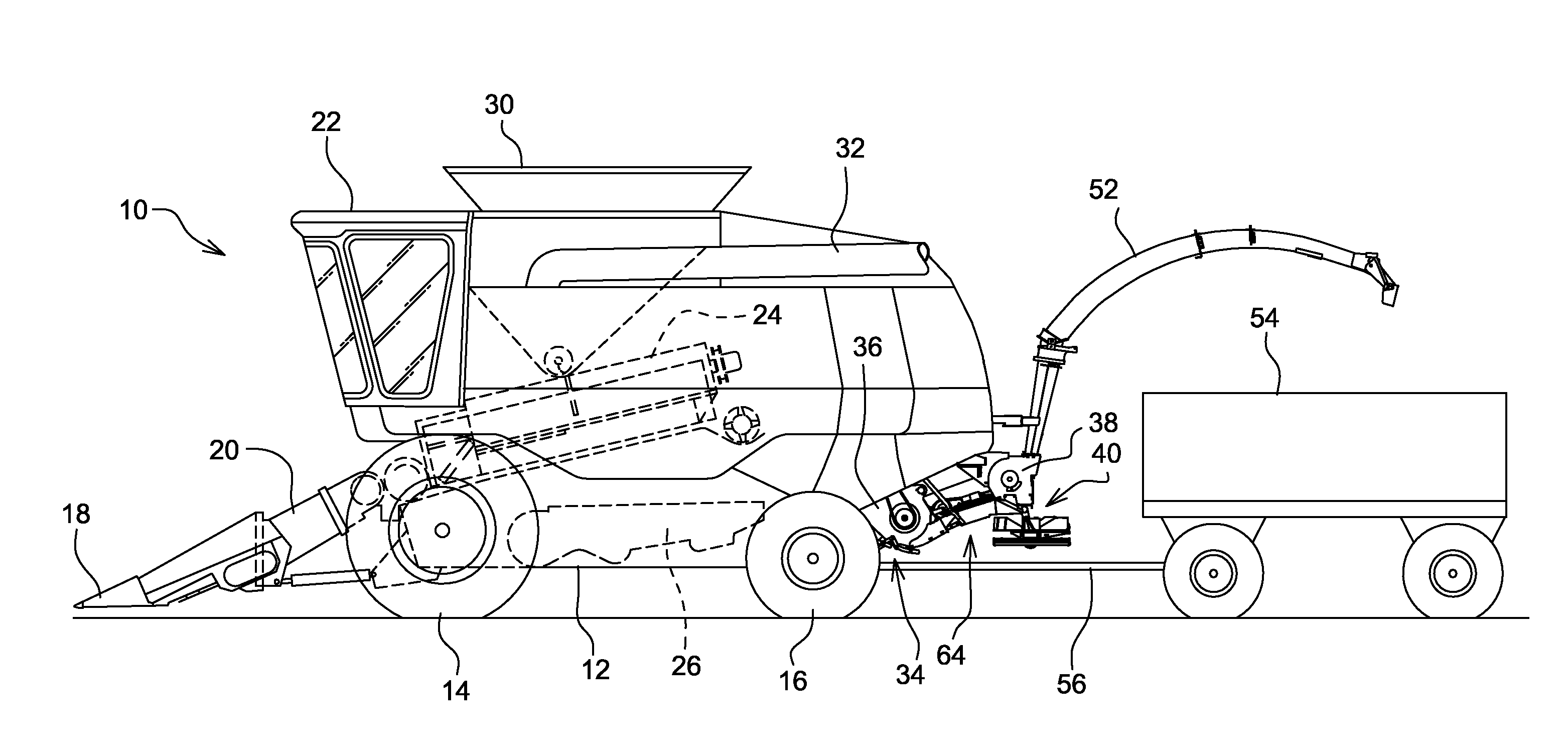
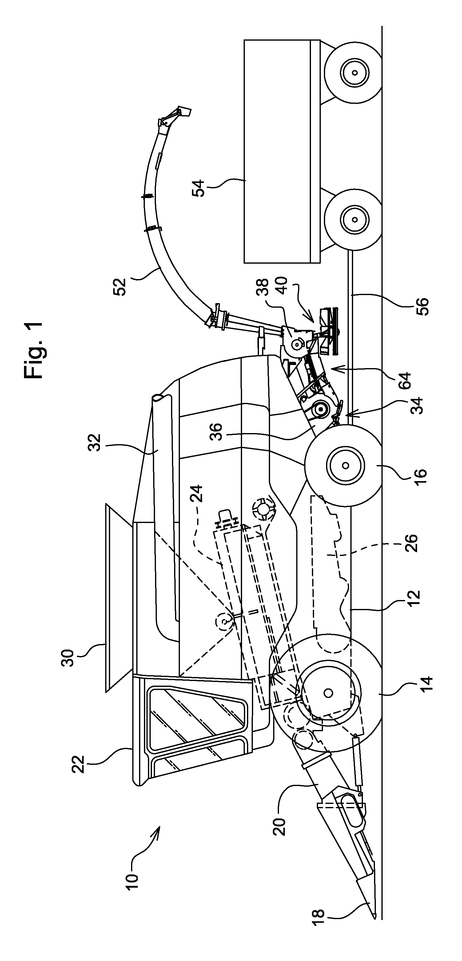
[0013]Referring now to FIG. 1, there is shown a self-propelled combine harvester 10 including a main frame 12 supported on front and rear sets of wheels 14 and 16, respectively. A harvester head 18 is mounted to a feeder house 20 carried at the forward end of the frame 12 so as to be in full view of an operator seated in a cab 22 mounted on the frame 12 above a rear end of the feeder house 20. Stalks or stems of the standing crop being harvested is cut by the harvesting head 18 and conveyed rearwardly, with the attached grain heads or ears, through the feeder house 20 which, in turn, delivers this crop matter to a threshing system 24 located just behind the feeder house and which, in turn, feeds the threshed crop material to a cleaning and separating system 26. Grain that is separated by the system 28 gravitates to the bottom of the system and is conveyed by a grain elevator (not shown) to a holding tank 30 from which the grain can be periodically transferred to a container carried ...


PUM


Abstract

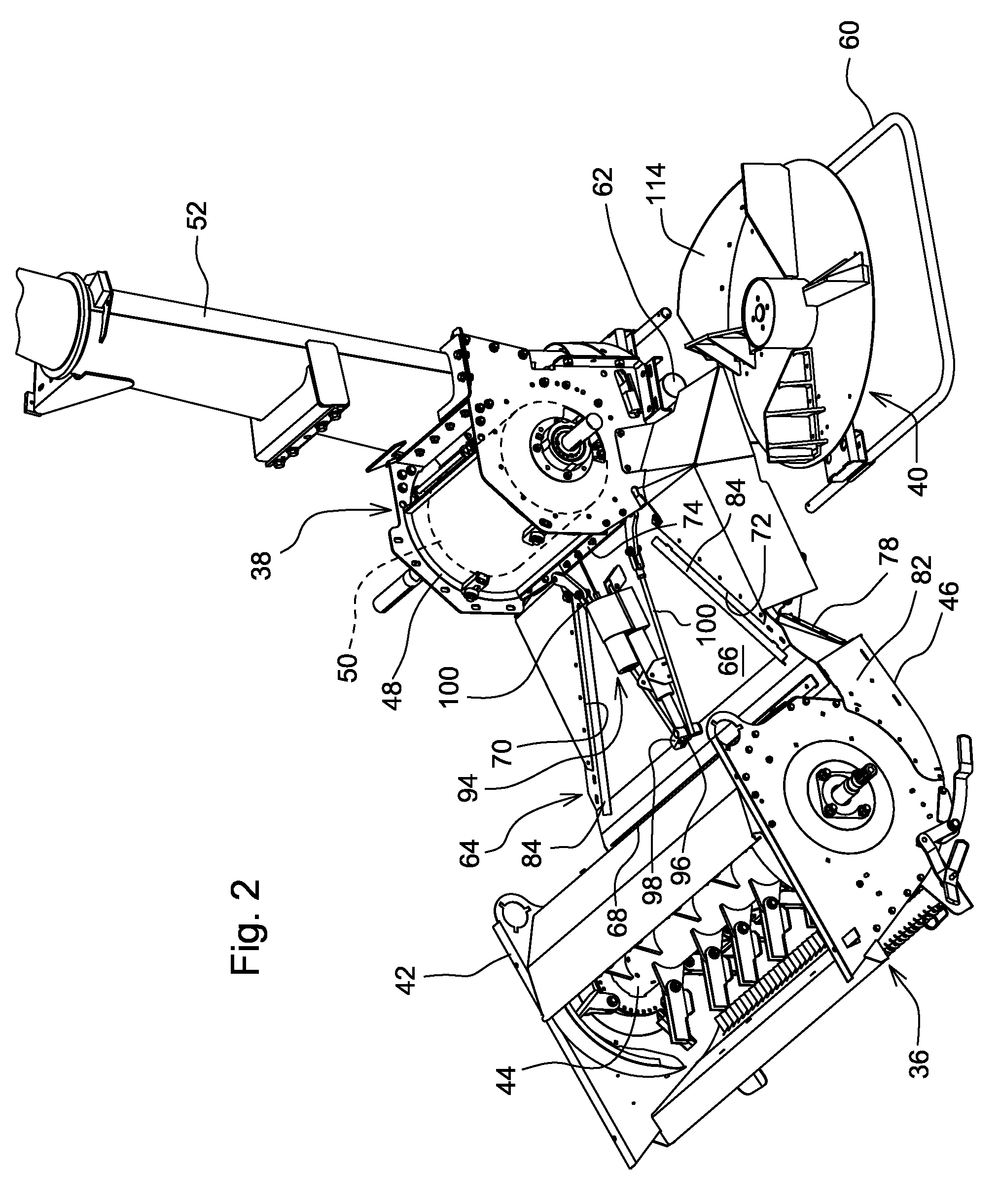
A crop residue handling device is mounted to the rear of a combine harvester for intercepting crop residue that remains after grain has been separated from the crop by the separator and cleaning arrangement of the harvester. The residue handling device includes a chopper which chops and impels the chopped residue rearwardly through a discharge duct. A transition duct receives the crop exiting from the chopper and contains upright deflector vanes mounted for pivoting and being automatically moved among desired positions, by a power actuator so as to direct desired proportions of the crop residue between a blower for receiving and accelerating the crop through a discharge chute for collection in a receptacle of a towed trailer, and a pair of spreader disks located at opposite sides of the blower for receiving and dispersing the crop residue on the ground.

Description

FIELD OF THE INVENTION[0001]The present invention relates to collecting crop residue discharged from a combine harvester, and more specifically relates to a way of diverting all or a selected portion of the crop residue from the collector so that it may be dispersed onto the ground.BACKGROUND OF THE INVENTION[0002]It is known to collect crop residue discharged from the back of a combine harvester and to convey the collected material into an in-field collection device. Further, it is known to provide a horizontal deflector door to split a flow of residue into upper and lower streams with the upper stream being collected and the lower stream being directed to spreader vanes which operate to disperse the lower stream onto the ground. A crop residue handling device of this type is disclosed in U.S. patent application Ser. No. 12 / 062,846, filed Apr. 4, 2008 and published as US 2008 / 0248843 on Oct. 9, 2008. This patent application discloses a control system for automatically varying the a...

Claims


Application Information

Patent Timeline
Patent Type & Authority Patents(United States)
IPC IPC(8): A01F12/30
CPCA01D41/1243A01F12/40
Inventor RITTER, AARON SCOTT
Owner DEERE & CO
Learn More