Residue splitter

a splitter and residue technology, applied in the field of agricultural combine and horizontal spreader assembly there, can solve the problems of uneven distribution of crop residue, increased rodent and insect habitat, uneven field warming and thawing, etc., and achieve the effect of better and more even distribution

Active Publication Date: 2009-06-30
BLUE LEAF I P INC
View PDF23 Cites 28 Cited by
  • Summary
  • Abstract
  • Description
  • Claims
  • Application Information

AI Technical Summary

Benefits of technology

[0007]There is thus disclosed herein a residue splitter apparatus, sometimes referred to hereinafter more simply as a residue splitter, for an agricultural combine that can be employed with a horizontal spreader apparatus and which is operable for discharging a flow of straw or other crop residue in a more sidewardly direction for a more uniform or even deposit on and over a field. More particularly, there is disclosed a residue splitter apparatus that includes a flow guide or distributor element that is positionable generally intermediate to the spreader paddles of the horizontal spreader apparatus and which includes crop residue flow surfaces on the leading sides of the flow guide element that extend rearwardly from a front edge portion and sidewardly to generally aft of at least portions of the spreader paddles to receive and direct the flow of crop residue from such spreader paddles. The residue splitter apparatus preferably also includes an adjustment mechanism that is operable to adjust the lateral expanse of the crop residue flow surfaces to controllably guide and direct the sidewardly flow of crop residue impinging the flow guide element by greater or lesser amounts. By so positioning the flow guide element and adjusting the lateral expanse of the crop residue flow surfaces, a user can alter and redirect a portion of the flow of crop residue from the horizontal spreader so as to effect a desired pattern of crop residue distribution from such spreader, such as to compensate for changing geographical and environmental conditions, in order that, under such conditions, a better and more even distribution of the crop residue may be realized over the entire width of the cut.

Problems solved by technology

With earlier spreaders, however, in many instances, uneven distribution of the crop residue occurred, with a greater or heavier concentration often being distributed nearer the center of the swath and a lesser or lighter concentration being distributed father sidewardly.
Such uneven distribution resulted in various problems such as, but not limited to, subsequent difficulty in passing fall tillage tools through residue clumps or thick areas, uneven insulation of the field, resulting in uneven field warming and thawing and subsequent uneven crop emergence during the following planting season, and other problems resulting from increased rodent and insect habitat.
However, such spreaders have continued to suffer from various shortcomings.
Many of such spreaders have exhibited a tendency to provide uneven crop residue distribution or coverage in the side-to-side direction over the swath, especially on uneven and varying terrain and in varying wind conditions.
Such constructions have been specifically designed for use with vertical crop residue spreaders, however, and not for use with horizontal spreaders, as a consequence of which, while more even crop residue distribution has been possible when vertical spreaders have been utilized, there has continued to be a problem with the distribution of crop residue when horizontal spreaders are employed.

Method used


Image

  • Residue splitter
  • Residue splitter
  • Residue splitter

Examples


Embodiment Construction

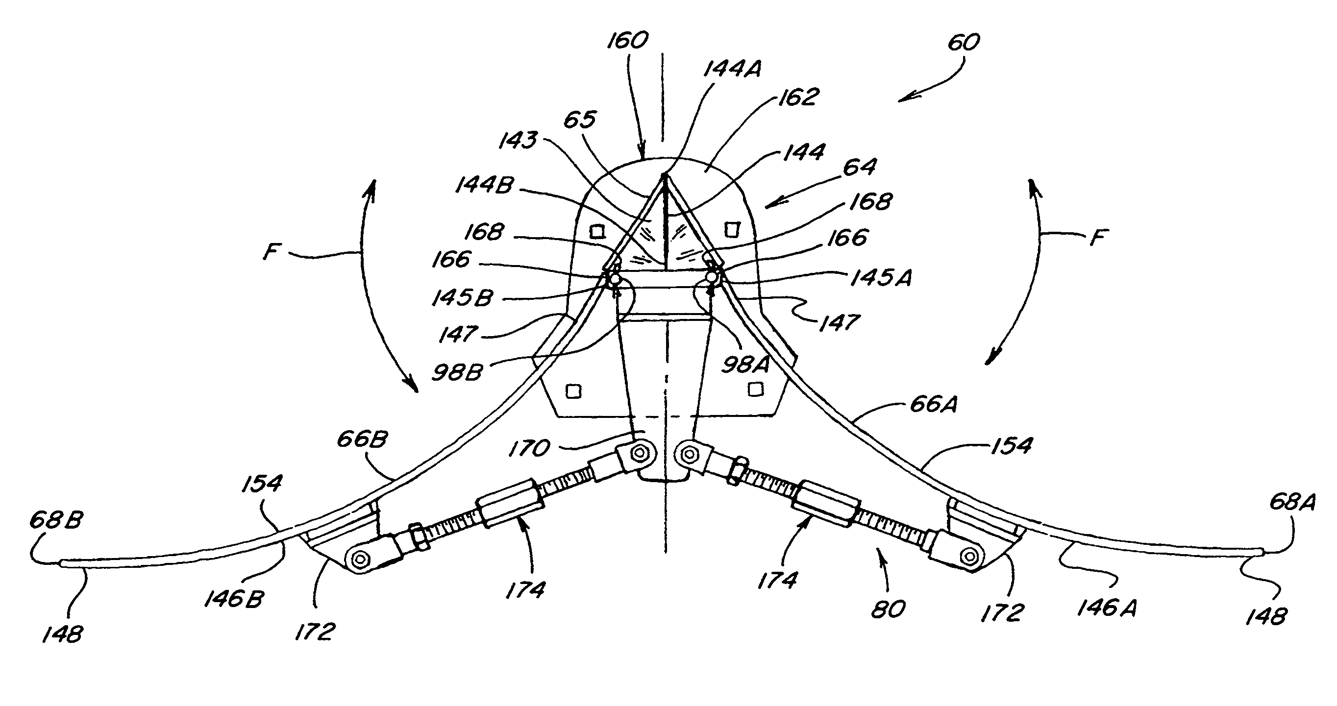
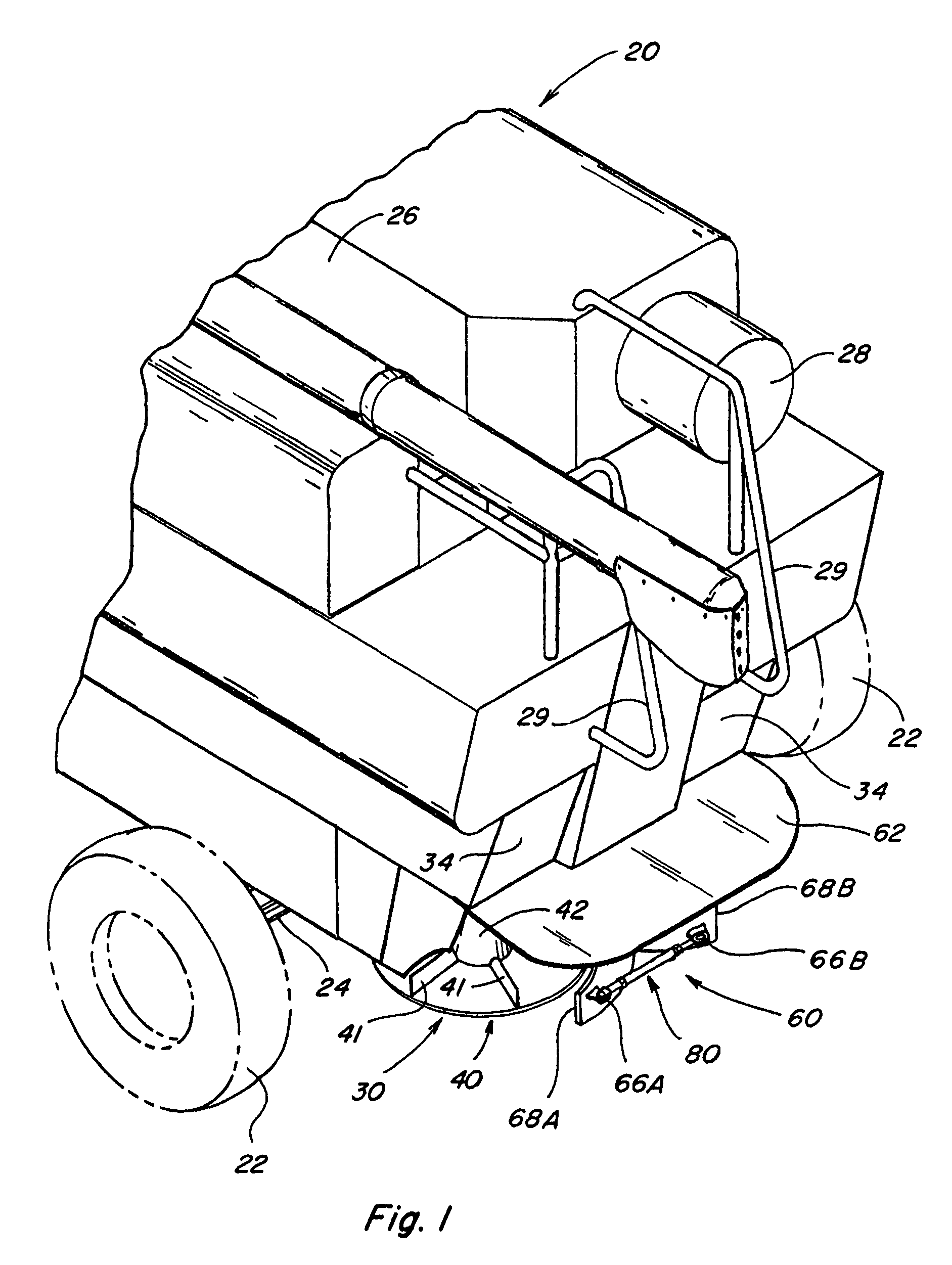
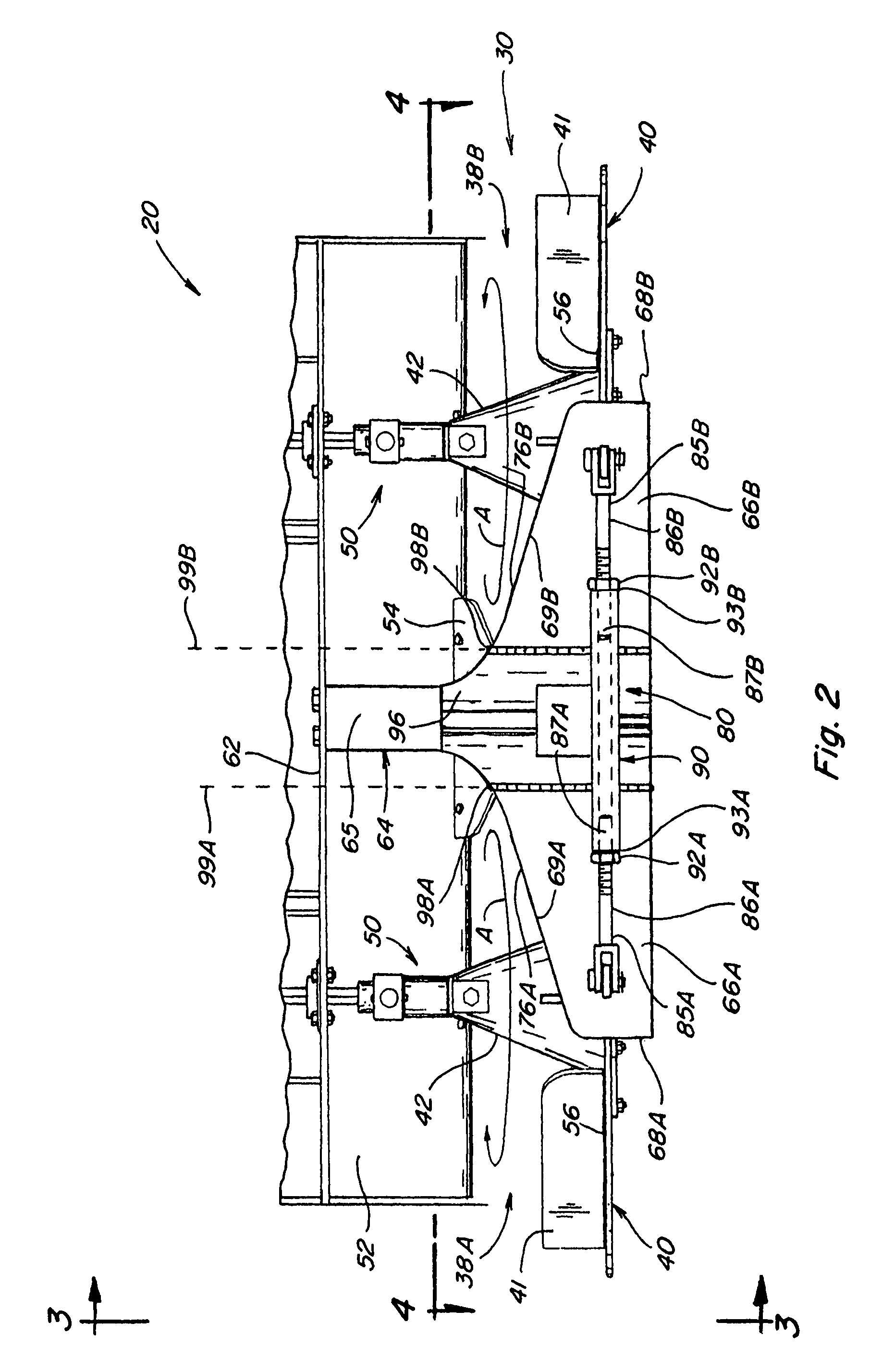
[0018]Referring now to the drawings, wherein like numerals refer to generally like items and wherein certain numerals are applied on a representational basis to selected, representative items of a class of like items instead of to all of the depicted like items, FIG. 1 depicts the rear portion of a typical combine 20 having a pair of rear tires 22 mounted upon a rear axle 24, with a grain auger or threshing rotor 26, an engine radiator air screen 28, and handrails 29 mounted upon the upper structure of the combine 20. A conventional horizontal spreader assembly 30, as better shown in FIGS. 2-4, is mounted generally below a crop residue discharge chute 32 (FIG. 3). For safety and other purposes, removable drive linkage cover plates 34 (FIG. 1) enclose associated drive linkages. When the threshing rotor 26 is operating, crop residue from such operation is discharged into discharge chute 32 which channels and directs the crop residue flow towards a pair of preferred spreader head assem...


PUM


Abstract

A residue splitter apparatus for use with a horizontal spreader assembly that employs a pair of spreader paddles disposed side-by-side to rotate about respective generally vertical axes for controlling the spread width distribution of crop residue on and over a field, and the method of use thereof, including a flow guide element located generally intermediate to the spreader paddles of the horizontal spreader assembly with crop residue flow surfaces that extend rearwardly from a front edge portion of the flow guide element and sidewardly to free end portions generally aft of at least portions of the spreader paddles to receive and direct the flow of crop residue from such spreader paddles. Preferably, the flow guide element is laterally expandable to permit the flow of crop residue from the spreader paddles to be adjustably varied to effect a desired pattern of crop residue flow from the spreader paddles, for instance, so as to better and more evenly distribute the flow side-to-side over a swath of an agricultural field from which the crop was harvested.

Description

TECHNICAL FIELD[0001]This invention relates generally to an agricultural combine and a horizontal spreader assembly therefor, and more particularly to a residue splitter apparatus for use with a horizontal spreader assembly for controlling the spread width distribution of straw or other crop residue in a sideward direction on and over a field, and the method of use thereof. More specifically, the invention relates to a residue splitter apparatus that includes a flow guide element for guiding and directing crop residue being discharged from a horizontal spreader assembly that employs a pair of spreader paddles disposed side-by-side to rotate about respective generally vertical axes. The front edge portion of the flow guide element is located generally intermediate to the spreader paddles of the horizontal spreader assembly and the flow guide element includes crop residue flow surfaces that extend rearwardly from the front edge portion and sidewardly to free end portions generally aft...

Claims


Application Information

Patent Timeline
Patent Type & Authority Patents(United States)
IPC IPC(8): A01F12/30
CPCA01D41/1243
Inventor LANDUYT, KOEN
Owner BLUE LEAF I P INC
Why Eureka
Try Eureka