Optical receiver using beam combining and system using the same
What is AI technical title?
AI technical title is built by PatSnap AI team. It summarizes the technical point description of the patent document.
a beam combining and optical receiver technology, applied in the field of laser systems, can solve the problems of increasing complexity of electronics and power dissipation, challenging laser signal reception, and increasing overall noise, and achieve the effect of maximizing the output signal
Inactive Publication Date: 2011-08-09
CELIGHT
View PDF9 Cites 0 Cited by
Summary
Abstract
Description
Claims
Application Information
AI Technical Summary
This helps you quickly interpret patents by identifying the three key elements:
Problems solved by technology
Method used
Benefits of technology
Benefits of technology
[0009]Yet another object of the present invention is to provide a system and method for information recovery, which can find applications in optical communications, remote sensing, optical imaging and other fields. The receiving unit includes an optical beam combiner with a set of input waveguides, each receiving a portion of incoming optical beam. 2M inputs of the combiner interfere with each other via a system of tunable coupled waveguides. The phases and the coupling ratios in interleaved waveguides of the combiner are adjusted to maximize the resulting output signal. The combiner may be used for coherent communication in combination with a balanced 90° hybrid. The receiving unit may be located as far as 2000 meters from the transmitter. The transmitter may include a light source that generates multiple wavelengths in the UV, optical or infrared ranges.
Problems solved by technology
Reception of the laser signal, however, is challenging because of the small number of scattered photons that make their ways to the receiver and also a substantial solar background radiation that mask the signal light.
Each photoreceiver add its own thermal and dark current noise to the signal independently such that the overall noise grows as the number of photoreceiver.
Furthermore, the complexity of the electronics and power dissipation increases as well.
Method used
Image
Click on the blue label to locate the original text in one second.
Reading with bidirectional positioning of images and text.
Examples
Embodiment Construction
[0016]The present invention now will be described more fully hereinafter with reference to the accompanying drawings, in which the preferred embodiments of the invention are shown. This invention may, however, be embodied in many different forms and should not be construed as limited to the embodiments set forth herein; rather, these embodiments are provided so that this disclosure will be thorough and complete, and will fully convey the scope of the invention to those skilled in the art.
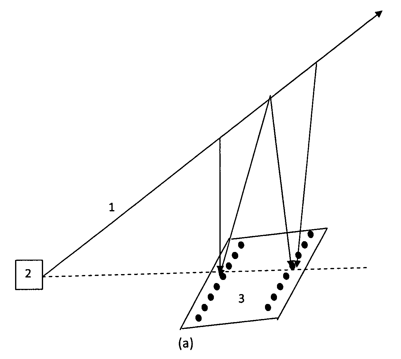
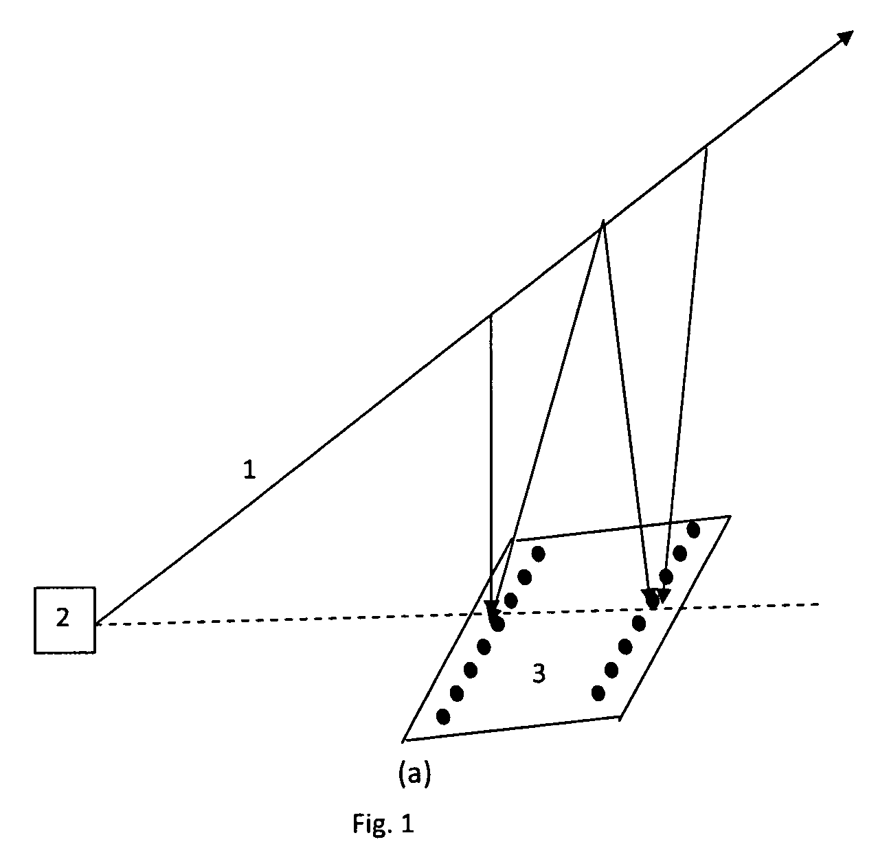
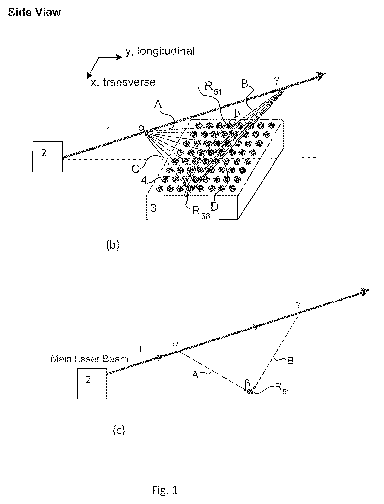
[0017]NLOS communications requires very sensitive receiving system, because of the small number of scattered photons that make their ways to the receiver and also a substantial solar background radiation that mask the signal light. Space-diversity via multiple aperture reception is an effective technique to mitigate the photon-starved transmission. An all-optical approach is disclosed here wherein multitude of transverse scattered optical beams captured by the multi-aperture array are combined first...
PUM
Abstract
An optical beam combiner is provided, which allows efficient collection of light for various applications: non-line of sight and free space optical communications, remote sensing, optical imaging and others. A multitude of transverse scattered optical beam portions is captured by the multi-aperture array positioned perpendicular to the beam projection direction. These beam portions are combined first into a single optical waveguide with minimal loss of power. This is achieved by modulating the beam portions phase and coupling ratio of couplers in the optical beam combiner tuned to maximize the final output power. The data is recovered from the received optical beam using coherent detection.
Description
CROSS-REFERENCE TO RELATED APPLICATIONS[0001]This application claims priority of provisional Application Ser. No. 61 / 090,404 filed Aug. 20, 2008. It is also a continuation-in-part of U.S. patent application Ser. No. 11 / 695,920 filed Apr. 3, 2007 now U.S. Pat. No. 7,715,720; Ser. No. 12 / 137,352 filed Jun. 11, 2008, Ser. No. 12 / 331,164 filed Dec. 9, 2008, which are continuation-in-part applications of U.S. Ser. No. 10 / 669,130 filed Sep. 22, 2003 now U.S. Pat. No. 7,327,913, Ser. No. 11 / 610,964 filed Dec. 14, 2006 now U.S. Pat. No. 7,397,979, Ser. No. 11 / 672,372 filed Feb. 7, 2007, all of which applications are fully incorporated herein by reference.FIELD OF THE INVENTION[0002]This invention relates generally to laser systems and methods of receiving at least a portion of the laser beam after its transmission through scattering media. The system includes an optical combiner for receiving at least portions of the scattered beam, combining them together and recovering data encoded in the...
Claims
Application Information
Patent Timeline
Application Date:The date an application was filed.
Publication Date:The date a patent or application was officially published.
First Publication Date:The earliest publication date of a patent with the same application number.
Issue Date:Publication date of the patent grant document.
PCT Entry Date:The Entry date of PCT National Phase.
Estimated Expiry Date:The statutory expiry date of a patent right according to the Patent Law, and it is the longest term of protection that the patent right can achieve without the termination of the patent right due to other reasons(Term extension factor has been taken into account ).
Invalid Date:Actual expiry date is based on effective date or publication date of legal transaction data of invalid patent.
Patent Type & AuthorityPatents(United States)
IPC IPC(8): G02B6/26H04B10/06H04B10/00
CPCB82Y20/00G02B6/1225G02B6/2808H04B10/61
InventorCHO, PAK SHINGSHPANTZER, ISAACKHURGIN, JACOB

