Magnetic Field Sensor Package

a magnetic field sensor and magnetic field technology, applied in the magnitude/direction of magnetic fields, semiconductor devices, single device manufacturing, etc., can solve the problems of insufficient mechanical displacement, signal may not be exactly detected, and the sensitivity of the magnetic field is decreased, so as to improve the sensing and resolution of the sensor, the distance between the magnetic field sensor and the conductive line can be minimized, and the effect of improving robustness

Active Publication Date: 2016-09-29
LG INNOTEK CO LTD
View PDF3 Cites 0 Cited by
  • Summary
  • Abstract
  • Description
  • Claims
  • Application Information

AI Technical Summary

Benefits of technology

[0021]According to the magnetic field sensor package according to the embodiment, since the distance between the conductive line serving as a current source and the magnetic field sensor is constantly maintained in the wafer level step, the distance between the conductive line and the magnetic field sensor is not changed depending on conditions, so that sensing can be exactly performed. In addition, the conductive line is inserted into the package or the chip, so that the distance between the magnetic field sensor and the conductive line can be minimized.
[0022]Therefore, according to the magnetic field sensor package according to the embodiment, the sensibility and the resolution of the sensor can be improved, so that robust can be improved against an unnecessary external magnetic field.
[0023]According to the embodiment of the disclosure, as the arrangement of the conductive line through which the current to be measured flows and the arrangement of the sensor assembly are optimized, the magnetic field is generated perpendicularly to the sensor assemblies, thereby minimizing the loss in the intensity of the magnetic field required to generate the Lorentz force.
[0024]According to the embodiment of the disclosure, an electromagnet is provided between a conductive line through which the current to be measured flows and the sensor assembly to increase the intensity of the magnetic field under the same current, so that the output signal of the magnetic field sensor can be maximized.
[0025]In addition, according to the embodiment of the disclosure, the direction of the magnetic field is formed perpendicularly to a reference current conductive line of the driving electrode, thereby obtaining a stable output value while reducing a probability that the driving electrode receives the Lorentz force in a different direction instead of the horizontal direction to abnormally drive.
[0026]In addition, according to the embodiment of the disclosure, the Lorentz force is concentrated in the horizontal direction, so that the displacement of the driving electrode can be maximized. Accordingly, the output value can be maximized for the same current and an equal intensity of the magnetic field, so that the resolution can be improved.

Problems solved by technology

However, since the Lorentz force used to sense the magnetic field is relatively significantly small as compared to gravity, the design for a sensor assembly including a spring is limited, so that it is difficult to obtain sufficient mechanical displacement.
In addition, as the distance between a conductor through which current to be measured flows and the sensor is increased, the sensitivity of the magnetic field is decreased, so that the signal may not be exactly detected.
If the displacement of the sensor assembly is reduced or abnormally driven as described above, the output single of the magnetic field sensor is reduced even under the current intensity, and the output value of the magnetic field sensor may be unstable.

Method used


Image

  • Magnetic Field Sensor Package
  • Magnetic Field Sensor Package
  • Magnetic Field Sensor Package

Examples


first embodiment

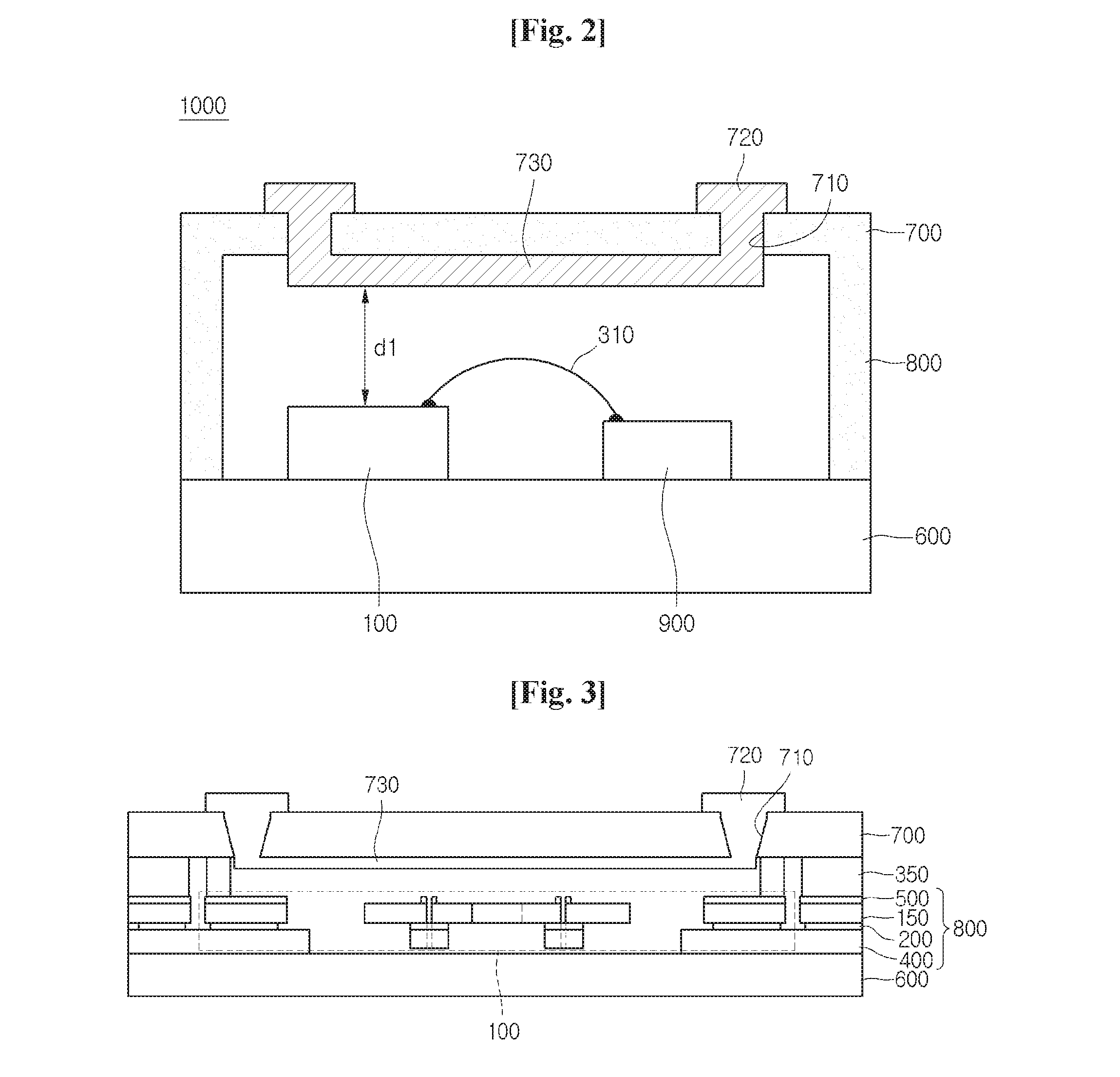
[0068]Referring to FIG. 2, a magnetic field sensor package 1000 according to the disclosure includes a magnetic field sensor of a MEMS device, and includes a package body 600, a magnetic field sensor 100, a control device 900, an upper layer 700, and a lateral side part 800.

[0069]The package body 600, which serves as a support substrate, may be formed of an insulating material. Specifically, the package body 600 may include multi-layer ceramic (MLC), a glass substrate, a resin substrate, or a heavily-doped silicon substrate.

[0070]The package body 600 is provided thereon with a plurality of devices.

[0071]The package body 600 may be provided thereon with the magnetic field sensor 100 and the control device 900.

[0072]The magnetic field sensor 100 and the control device 900 may be arranged in line with each other as shown in FIG. 2, but the disclosure is not limited thereto. In other words, the magnetic field sensor 100 and the control device 900 may be variously arranged depending on d...

second embodiment

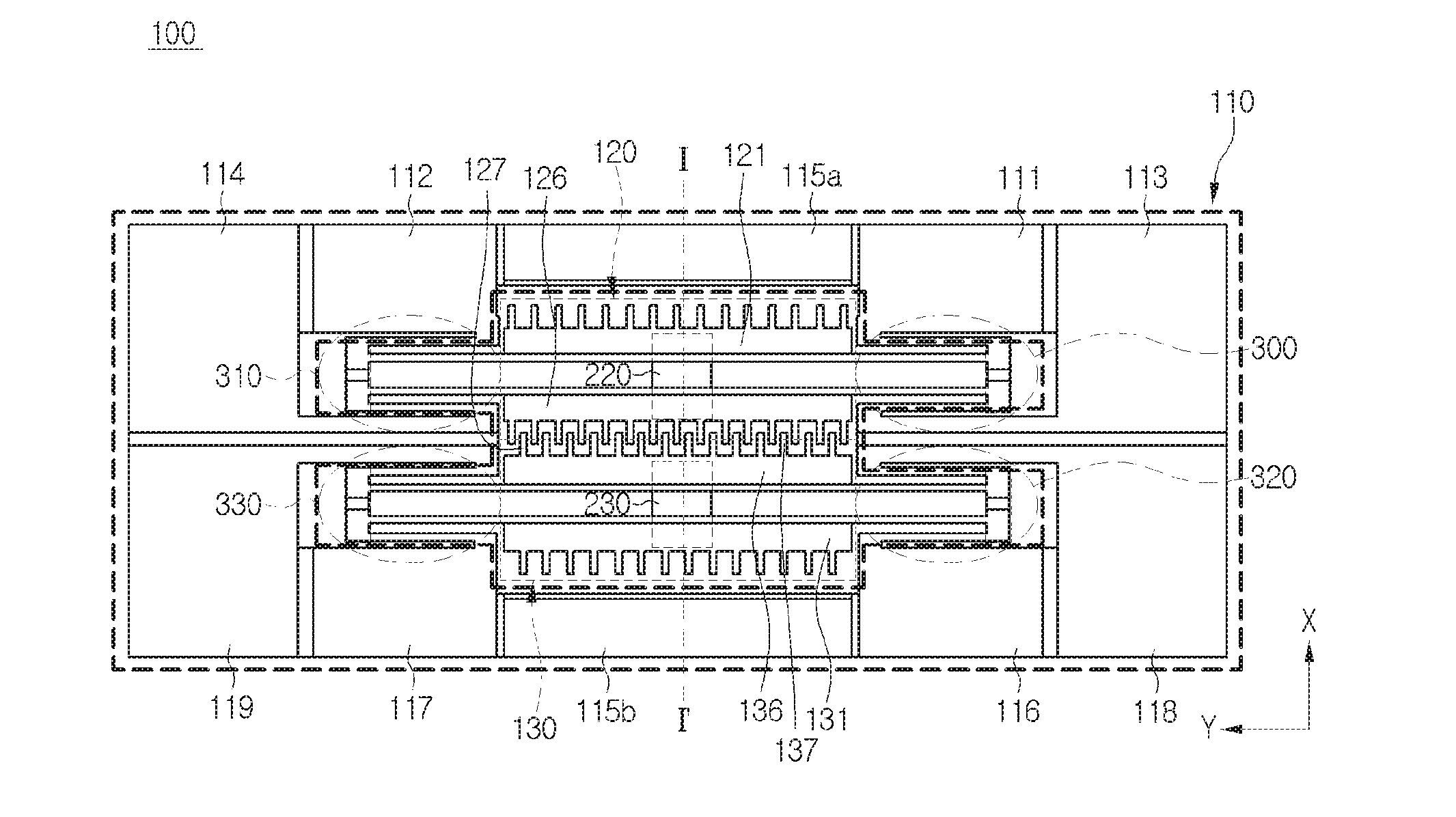
[0239]FIG. 18 is a top view showing a MEMS magnetic field sensor package according to the disclosure. FIG. 19 is a first sectional view taken along line A-N of THE MEMS magnetic field sensor package of FIG. 18. FIG. 20 is a second sectional view taken along line A-A′ of the MEMS magnetic field sensor package of FIG. 18. FIG. 21 is a top view showing the magnetic field sensor shown in the magnetic field sensor package of FIG. 18.

[0240]Among them, FIG. 19 is a first sectional view taken along line A-A′ of the MEMS magnetic field sensor package of FIG. 18. FIG. 20 is a second sectional view taken along line A-A′ of the MEMS magnetic field sensor package of FIG. 18, different from the embodiment of FIG. 19.

[0241]Referring to FIGS. 18 to 20, a magnetic field sensor package 1300 according to the embodiment includes a magnetic field sensor 1100 of a MEMS device, a package body 1210, a conductive line pad 1220, a conductive line 1230, a control device 1240, a connection line 1250, and a pro...

third embodiment

[0315]FIG. 26 is a top view showing a MEMS magnetic field sensor package according to the disclosure. FIG. 27 is an enlarged top view showing a conductor and a sensor assembly shown in FIG. 20. FIG. 28 is a second sectional view taken along line A-A′ of the magnetic field sensor package of FIG. 26.

[0316]Referring to FIG. 26, the MEMS magnetic field sensor package according to the third embodiment of the disclosure includes a magnetic field sensor 1100, a package body 1210, a wire pad 1220, a conductive line 1430, a control device 1240, a connection line 1250, and a protective layer 1260.

[0317]In the MEMS magnetic field sensor package 1400 shown in FIG. 26 according to the third embodiment of the disclosure, the same reference numerals will be assigned to the same components of those of the MEMS magnetic field sensor shown in FIG. 18 according to the first embodiment of the disclosure.

[0318]Since the magnetic field sensor 1100, the package body 1210, the wire pad 1220, the control de...


PUM


Abstract

A magnetic field sensor package according to an embodiment includes: a package body; a magnetic field sensor disposed on top of the package body and including a sensor assembly in which a displacement is generated by a magnetic field; and a conductive line formed on the package body, which is for making current to be measured flow and generating a magnetic field for displacing the sensor assembly, wherein the conductive line generates a magnetic field applied in a perpendicular direction to the sensor assembly.

Description

TECHNICAL FIELD[0001]The embodiment relates to a magnetic field sensor package, and more particularly to a MEMS magnetic field sensor package.BACKGROUND ART[0002]In general, a magnetic field sensor based on a MEMS (micro electro mechanical systems) capacitive sensing technology includes a driving electrode movable in reaction to a magnetic field and a fixing electrode to sense capacitance variation corresponding to the movement of the driving electrode.[0003]According to the principle on the magnetic field sensor, when reference current is applied to the driving electrode in a predetermined direction, the driving is moved from the fixing electrode in a positive or negative direction due to the Lorentz force based on the direction and the intensity of an external magnetic field.[0004]In this case, the variation in the distance between two electrodes or the overlap area between the two electrodes is made to vary the capacitance. The variation of the capacitance or the signal varied co...

Claims


Application Information

Patent Timeline
Patent Type & Authority Applications(United States)
IPC IPC(8): G01R33/06
CPCG01R33/06G01R33/0052H01L2224/48145H01L2224/48137H01L2224/49175H01L2224/48091H01L2924/00014
Inventor SEO, SANG WONSEO, JEONG GIKIM, CHULKO, YONG JUNCHOI, WAN SEOP
Owner LG INNOTEK CO LTD
Why Eureka
Try Eureka