Methods and apparatus for measuring flexural wave and/or flexural vibration using a magnetostrictive sensor

a technology of flexural wave and magnetostrictive sensor, which is applied in the direction of vibration measurement in solids, instruments, specific gravity measurement, etc., can solve the problem of too small sensor output for accurate measurement, and achieve the effect of optimizing the topology of bias magnet and bias yoke, accurate measurement, and maximizing output signal

Inactive Publication Date: 2005-03-22
SEOUL NAT UNIV R&DB FOUND
View PDF5 Cites 6 Cited by
  • Summary
  • Abstract
  • Description
  • Claims
  • Application Information

AI Technical Summary

Benefits of technology

It is preferred that the bias magnet and the bias yoke have optimized shapes to maximize the output signal of the magnetostrictive sensor.
It is preferred that the bias magnet is a fixed electromagnet, and the bias yoke has an optimized shape for maximizing the output signal of the magnetostrictive sensor.
It is preferable to optimize the topology of the bias magnet and bias yoke to maximize the output signal of the magnetostrictive sensor.
It is preferable to optimize the topology of the bias yoke only, when the fixed electromagnet is used as a bias magnet, to maximize the output signal of the magnetostrictive sensor.
The present invention provides an apparatus or a method for measuring flexural waves and / or vibrations using a magnetostrictive sensor, wherein large sensor outputs can be obtained, accurate measurement is possible, the fabrication of the sensor is simple, and the adjustment of sensor efficiency is easy.

Problems solved by technology

But in this case the sensor output was too small to conduct the accurate measurement.

Method used


Image

  • Methods and apparatus for measuring flexural wave and/or flexural vibration using a magnetostrictive sensor
  • Methods and apparatus for measuring flexural wave and/or flexural vibration using a magnetostrictive sensor
  • Methods and apparatus for measuring flexural wave and/or flexural vibration using a magnetostrictive sensor

Examples


first embodiment

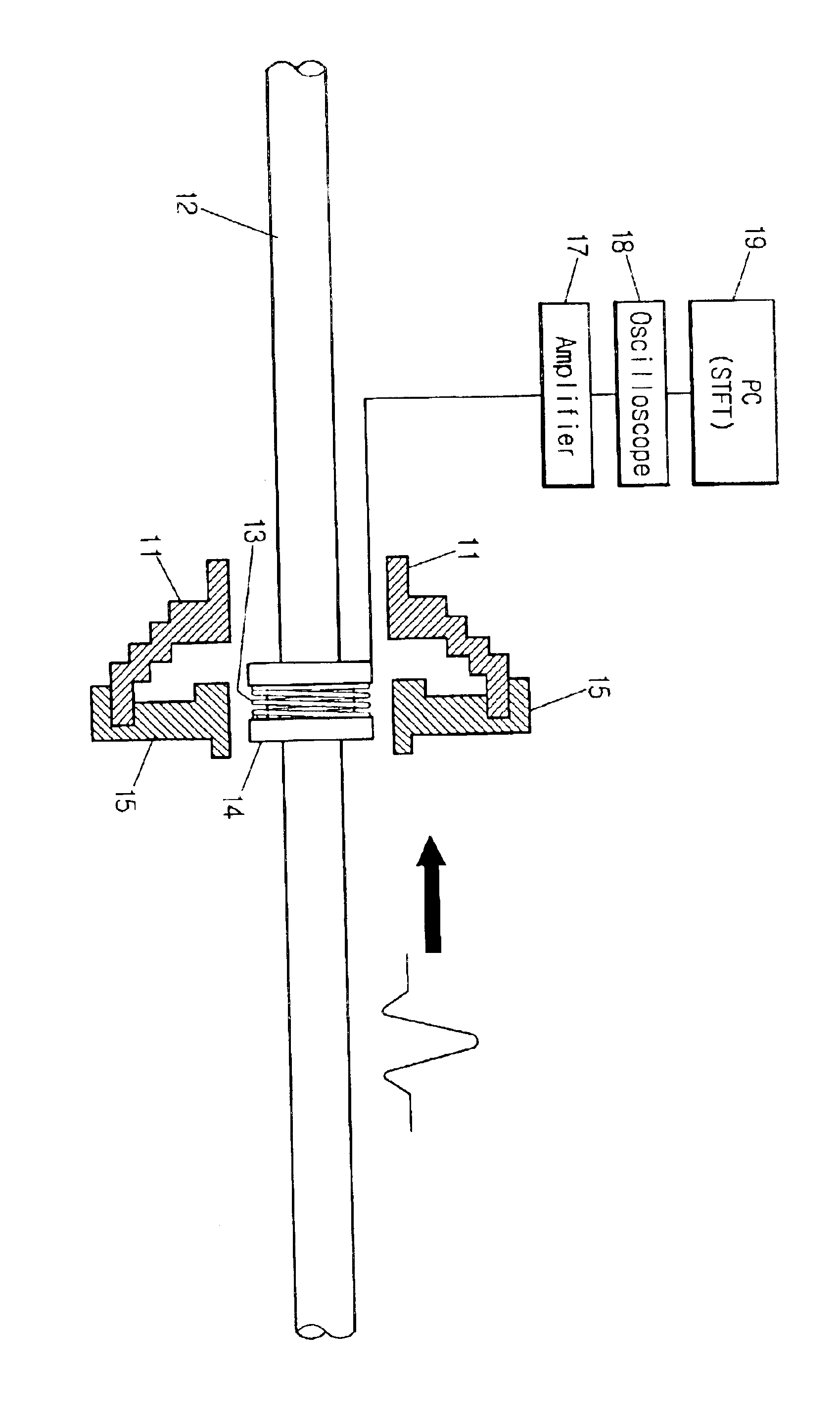
A first embodiment of the present invention illustrates an apparatus and the method of maximizing the output signal of the sensor by optimizing the bias magnets of the magnetostrictive sensor when the flexural wave propagates. In the present invention, the density method and OC (Optimality Criterion) have been adopted as an optimization strategy.

In the first place, the magnetostrictive effect is modeled and expressed as the following equation 1.

B=qσ+μH  [equation 1]

where μ represents the permeability, q, the magneto-elastic coupling coefficient, B, the magnetic induction, and H, the magnetic field strength applied by the bias magnet.

The time-variation of the magnetic induction can be measured by Faraday-Lentz's law. The second term of equation 1 can be ignored in evaluating the voltage output of the pick-up coil. Therefore, the output voltage ν of the pick-up coil can be written as the following v=-N⁢∫A⁢ⅆBⅆt⁢ ⁢ⅆA=CN⁢∫A⁢ⅆσⅆt⁢ ⁢ⅆA[equation⁢ ⁢2]

where C denotes some constant, N, the num...

second embodiment

the present invention uses an electromagnet of a fixed size as a bias magnet to facilitate the manufacturing of the magnetostrictive sensor, and maximizes the output signal of the sensor by optimizing the topology and the shape of bias yoke of the magnetostrictive sensor. In the second embodiment, the density method and OC (Optimality Criterion) have been applied as optimization techniques, as in the case of first embodiment. Unlike the first embodiment, however, the nonlinearly varying magnetic permeability is also considered in the second embodiment.

In maximizing the voltage output of sensor for the second embodiment, the volume constraint condition is expressed as equations 3 and 4 used for the first embodiment. However, in the second embodiment; only the bias yoke is optimized, where the magnetic permeability of the yoke is modeled as equation 12.

μ=μ0{1+(μ3−1)ρn}  [equation 12]

where μ3 denotes the permeability of the bias yoke.

In case where the bias yoke is assumed to behave lin...


PUM

PropertyMeasurementUnit
magnetic fieldaaaaaaaaaa
ferromagneticaaaaaaaaaa
magnetic field distributionaaaaaaaaaa

Abstract

Disclosed is an apparatus or a method for measuring flexural waves and / or vibrations acting on ferromagnetic materials or ferromagnetic films. The present invention includes a bias magnet disposed around the ferromagnetic material so as to form a magnetic field in accordance with a stress distribution pattern occurring as the flexural wave propagates along the above said ferromagnetic material, and a measuring device for measuring the time-varying change of the magnetic induction resulting from the propagation of flexural waves on the ferromagnetic material. In addition to the above components, the bias yoke can be disposed around the ferromagnetic material to support the function of the magnet and the formation of the magnetic circuit as a measuring device for the change of the magnetic induction. In addition, a fixed electromagnet can be used as the bias magnet.

Description

BACKGROUND OF THE INVENTION1. Field of the InventionThe present invention is related to an apparatus for measuring flexural waves and / or flexural vibrations using a magnetostrictive sensor and the method thereof, which, in particular, disposes the bias magnet configuration to form the magnetic field around ferromagnetic materials and measures flexural waves and / or flexural vibrations from the time-varying change of the magnetic field in ferromagnetic materials resulting from the Inverse Magnetostrictive Effect.2. Background of the Related ArtWhen a ferromagnetic material is subjected to a mechanical force, the internal magnetic status of the material changes, which is called the Inverse Magnesotrictive Effect or the Villari Effect. This is the inverse phenomenon of the Joule Effect, where a ferromagnetic object in a magnetic field, undergoes its dimensional change according to the direction of the magnetic field.The magnetostrictive sensor (Mss) is ordinarily used as a measuring mea...

Claims


Application Information

Patent Timeline
Patent Type & Authority Patents(United States)
IPC IPC(8): G01H11/00G01H11/04G01R9/06
CPCG01H11/04G01R9/06
Inventor KIM, YOON YOUNGCHO, SEUNG HYUNKIM, YOUNG KYUKIM, WOO CHUL
Owner SEOUL NAT UNIV R&DB FOUND
Why Eureka
Try Eureka