Clasp for band

a technology for clasps and bands, applied in the field of clasps, can solve the problems of not meeting the requirements of safety in maintaining the adjustment, or the ease of adjustment of prior-art inventions

Active Publication Date: 2011-08-23
ROLEX SA
View PDF8 Cites 22 Cited by
  • Summary
  • Abstract
  • Description
  • Claims
  • Application Information

AI Technical Summary

Benefits of technology

[0010]The principal advantage of the clasp of the invention is that it makes the translational guidance as precise as the guides used in precision instruments and machines. With such guidance it is possible to slide the connecting member smoothly and without sticking when adjusting the length. This is particularly important where the range of adjustment is large, as is particularly the case when it comes to an adjustable clasp for a diving watch band, which has to be able to adapt both directly to the diver's wrist and indirectly to the diving suit, which represents a difference of several centimeters around the wrist.
[0011]Advantageously, one of the two parts of the positioning device is mounted on a hinge pin extending transversely relative to the long arms of the clasp, to bring about relative movement between the plurality of positioning elements and the immobilizing element for the purposes of engaging and disengaging them with each other.

Problems solved by technology

As can be seen, none of the prior-art inventions meets the requirements of safety in maintaining the adjustment, or of ease of adjustment, while simultaneously allowing the clasp to be used like a normal clasp when it is not wished to modify the adjusted length.

Method used


Image

  • Clasp for band
  • Clasp for band
  • Clasp for band

Examples


second embodiment

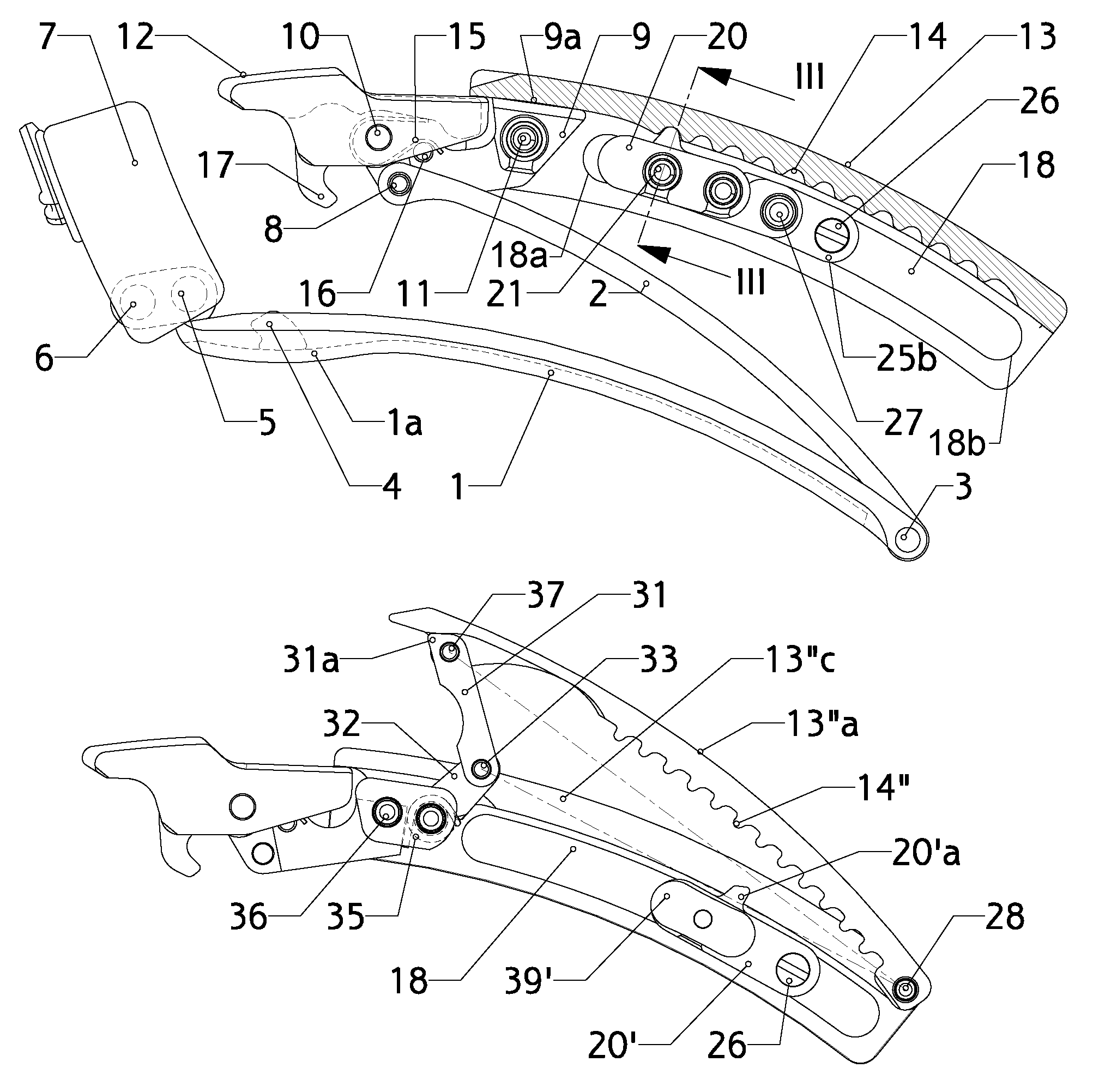
[0039]The second embodiment, illustrated in FIGS. 7, 8 and 9, differs from the first only in that the tooth 20′a is not now integral with an immobilizing element pivoting on the bar 21, the immobilizing element 20′a being stationary, and the bar 21 extends through it. To engage and disengage the immobilizing tooth 20′a relative to the teeth 14′ of the rack, the rack is on a flap 13′a independent of the bottom of the U of the cover 13′ which is formed by two parallel parts, a front part 13′b and a rear part 13′c separated from one another by the breadth of the flap 13′a and joined by hinge pins, including a transverse hinge pin 28 on which one end of the flap 13′a pivots.

[0040]The other end of the flap 13′a is hinged about a transverse hinge pin 40 to a control lever 29 which has one end pivoting on the cover 13, about a transverse hinge pin 30. The other end 29a of this control lever 29 projects, when the adjacent end of the cover 13′ is down (FIG. 7), to provide a means of lifting ...
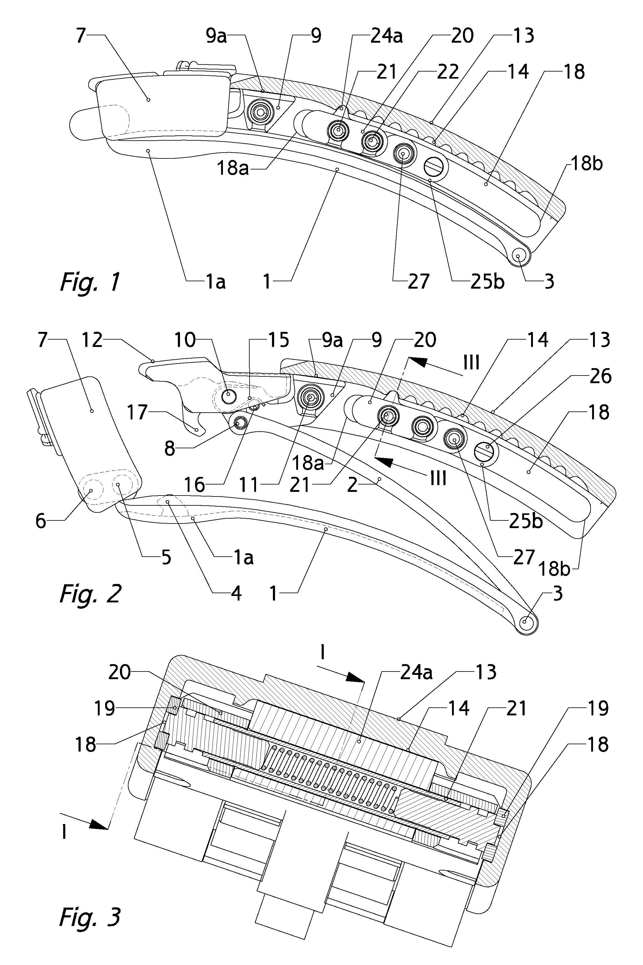
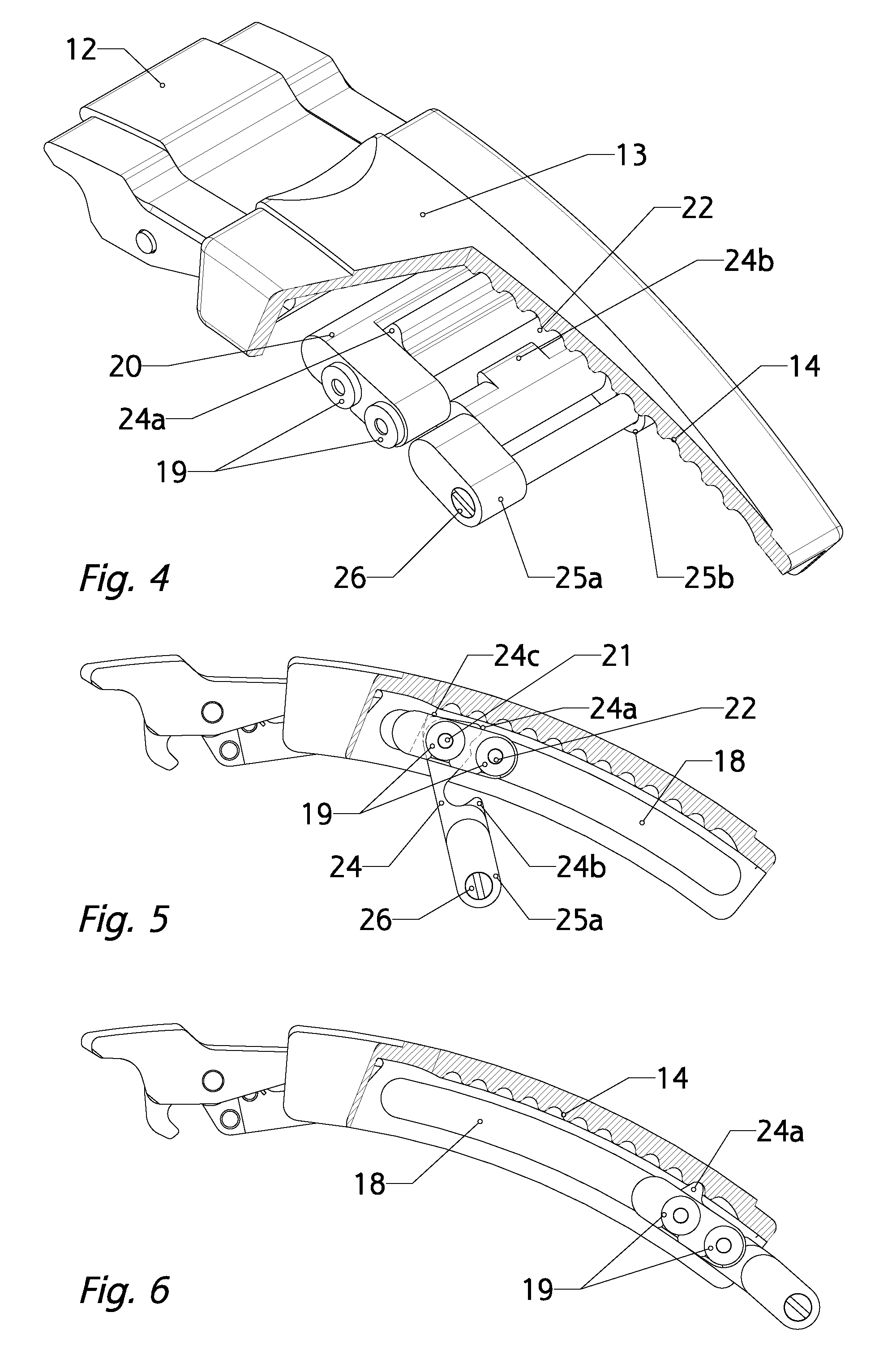
first embodiment

[0046]Naturally, it is perfectly possible to replace the rollers 19 of the first embodiment with the sliding shoes 39, 39′ and vice versa. The forces of friction on the sliding shoes 39, 39′ can be adjusted through the lateral forces applied to these sliding shoes 39, 39′ by the spring bar 21.


PUM


Abstract

A clasp including long hinged arms (1, 2, 13), a mechanism for adjusting the longitudinal position of the connecting member (20) connecting one of the free ends of the band to one of the long arms (1, 2, 13), having two tracks (18) defining two corresponding paths extending in two planes parallel to the longitudinal axis of the arms (1, 2, 13), and sliding elements (19, 39) for engaging with the respective guide tracks (18), the respective cross sections of the tracks and of the sliding elements including complementary adjacent surfaces to limit the movement of the sliding elements (19, 39) to one degree of freedom corresponding to the sliding path of the tracks (18), in such a way as to ensure free translational movement of the connecting member.

Description

[0001]The present invention relates to a clasp for a band, such as a wristwatch band, comprising at least two long arms that pivot on each other about transverse hinge pins at one of their respective longitudinal ends, a locking device for keeping the free ends of these two long arms in the folded position, connecting members for connecting the long arms to the respective ends of a band, and a mechanism for adjusting the longitudinal position of the connecting member connecting one of the free ends of the band to one of the long arms having on the one hand a sliding device comprising guide elements integral with a first one of the long arms, extending essentially longitudinally to this arm, two stops for defining the active length of said guide elements, sliding elements integral with the connecting member connecting one of the ends of the band to this first long arm, engaged with the guide elements, and on the other hand a positioning device, of which a first part has a plurality o...

Claims


Application Information

Patent Timeline
Patent Type & Authority Patents(United States)
IPC IPC(8): A44C5/18
CPCA44C5/246Y10T24/4782Y10T24/2155
Inventor CHRISTIAN, MARTINLEMOSQUET, VINCENT
Owner ROLEX SA
Why Eureka
Try Eureka