
Pin tumbler lock releasing system

a technology of pin tumbler locks and locking pins, which is applied in the field of pin tumbler lock release systems, can solve the problems of difficult lock bumping, difficult lock picking, and difficult lock picking, and achieve the effect of equal effectiveness

Inactive Publication Date: 2011-08-23
BLACK CARL
View PDF9 Cites 8 Cited by
  • Summary
  • Abstract
  • Description
  • Claims
  • Application Information

AI Technical Summary

Benefits of technology

[0008]It is an object of the present invention to provide a method for actuating release of any lock that employs a pin tumbler mechanism, and for doing so without the intended key. It is a further object that such a method be able to be practiced in an identical manner with equal effectiveness on a variety of pin tumbler locks, despite differences in their total numbers of tumbler pin stacks (e.g., 3-pin, 4-pin, 5-pin, etc.) and irrespective of their outer casing configurations (cylinders, padlocks, etc.).
[0009]It is an associated object of the present invention to provide at least one combination instruments that a person possessing no adeptness whatsoever at lock picking can easily use to practice the instant lock releasing method.

Problems solved by technology

Moreover, because the key pins are not all uniform in length (the driver pins are), when a key that is not cut to operate with the specific lock at hand is inserted into the keyway, one or more of the key pins and / or driver pins will be positioned straddling the shear line.
This precise alignment of the pin contact surfaces with the shear line renders the pin stacks ineffective in inhibiting plug rotation so that the locking mechanism can be released by delivering torque to the plug via the key.
In situations in which a pin tumbler lock must be opened, but a properly cut key is not available to the lock owner, the owner or a locksmith will likely be forced to either destroy the lock or employ a lock “picking” or “bumping” technique in order to open a lock.
Depending on the sophistication of the particular tools used, lock picking can be a tedious proposition simply due to the incremental manner in which each pin stack must be properly aligned with the shear line before the locking mechanism can be released.
Lock bumping can also be difficult due to the delicateness and precise timing that may be needed in applying to the key pins an impact force of appropriate magnitude and direction to cause the desired separations of the key pins and driver pins about the shear line while also initiating plug rotation during the fleeting moment in which the pins are so displaced.

Method used


Image

  • Pin tumbler lock releasing system
  • Pin tumbler lock releasing system
  • Pin tumbler lock releasing system

Examples


Embodiment Construction

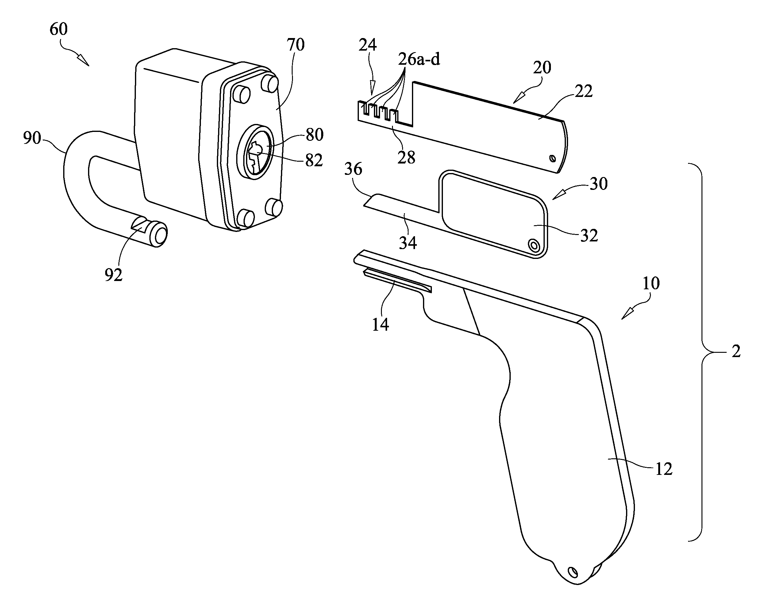
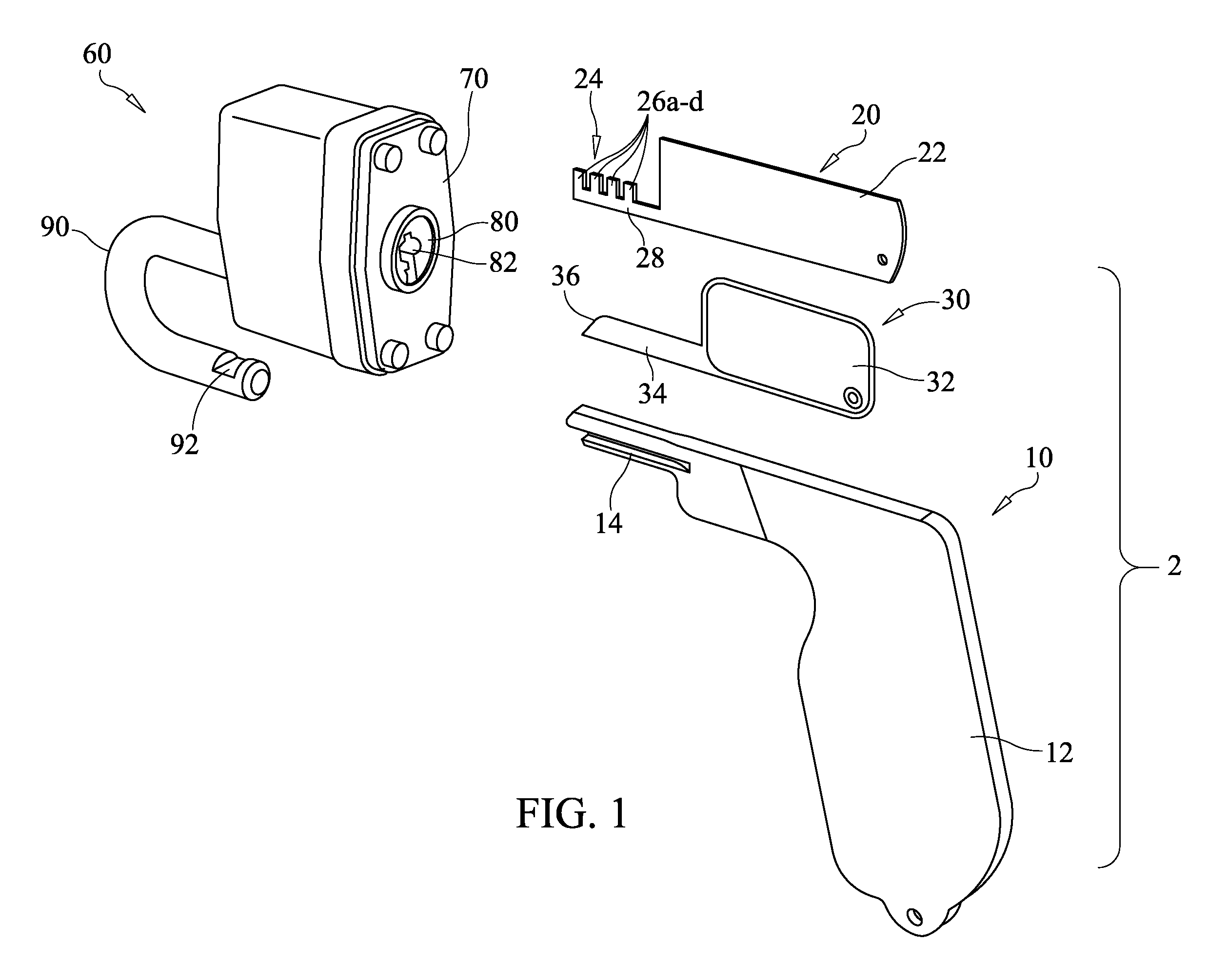
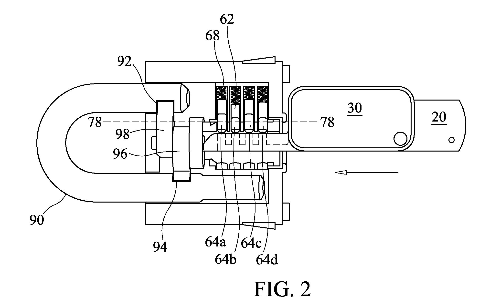
[0023]This disclosure, as defined by the claims that follow and as illustrated, by way of example, in the accompanying drawings, relates to an apparatus system and method for releasing pin tumbler-type locks. Most of the accompanying drawings depict the system being used on a pin tumbler padlock 60. This particular lock60 comprises a cylindrical plug 80 disposed within an outer casing 70. The lock 60 has a keyway 82 and four pin stacks that each comprise a driver pin 68 and a key pin 64 disposed within aligned vertical apertures, or “tumbler pin holes,” formed within both its plug 80 and casing 70. Coil springs 68 are mounted to both the closed top ends of the pin holes and the driver pins 68 to bias both pins 68, 64 downward. The lock 60 also features a locking mechanism comprising a pair of oppositely oriented cams 96, 98 that pivot, upon rotation of the plug 80, to lock and release a spring-loaded shackle 90. Nevertheless, pin tumbler locks adapted for use with dwelling doors (in...


PUM


Abstract

A pin tumbler lock releasing system includes keyway insertible and universally configured lift, key and shim devices that cooperatively work to raise the pin stacks within a pin tumbler lock to just above the pin tumbler lock's shear line so that its plug element may be rotated within its outer casing in order to disengage its locking mechanism.

Description

[0001]This nonprovisional application claims the benefit of provisional application 61 / 113,550.BACKGROUND OF THE INVENTION[0002]The present invention generally relates to devices used for non-destructive lock picking, and it is specifically directed to a system of tools used for releasing a lock of the “pin tumbler” type in a novel fashion that neither damages the lock nor requires use of a typical lock key.[0003]Pin tumbler locks generally feature four primary components: an outer casing, a plug, a locking mechanism and a series of parallel pin stacks. Formed through the casing is a cylindrical bore within which the cylindrical plug is rotatably housed. Opening at the front end of the plug is a slot, or “keyway,” that extends axially into it and is configured to receive a key having a specific cut. At the rear end of the keyway typically is a lever or cam arrangement that actuates the locking mechanism to engage or release the lock upon relative rotation of the plug and casing. For...

Claims


Application Information

Patent Timeline
Patent Type & Authority Patents(United States)
IPC IPC(8): E05B19/20E05B27/04
CPCE05B19/20E05B67/24Y10T70/7599Y10T70/7797Y10T70/7802
Inventor BLACK, CARL
Owner BLACK CARL
Learn More