Winder Cable Guard

a winder and cable technology, applied in waterborne vessels, hoisting equipment, thin material handling, etc., can solve the problems of cable pinching, wedged or jammed between the winder drum, cable cannot travel smoothly, and the conventional boat lift winder mechanism experiences operating problems, etc., to achieve the effect of reducing significant damage, reducing inconvenience and expense, and improving winder operation

Active Publication Date: 2017-05-11
GOLDEN WILLIAM
View PDF7 Cites 4 Cited by
  • Summary
  • Abstract
  • Description
  • Claims
  • Application Information

AI Technical Summary

Benefits of technology

[0007]It is a further object of this invention to provide a cable winder guard designed to reduce the significant damage, delays, inconvenience and expense commonly caused by the boat lift cable becoming caught, jammed or pinched between the winder and support bearing.
[0008]It is a further object of this invention to provide a cable winder guard that causes a lift cable to be wound in a more uniform, consistent, even and tangle-free manner on a winder so that winder operation is improved considerably.
[0009]It is a further object of this invention to provide a cable winder guard that may be utilized with equal effectiveness on both newly manufactured winder mechanisms and on existing winders that are retrofit with the cable guard.
[0010]It is a further object of this invention to provide a winder cable guard that is especially effective for use on boat lift winders but which also may be used effectively in other industries.
[0011]This invention features a cable guard for a winder mechanism. The winder mechanism includes an elongate winder drum that is supported on a central shaft. The shaft is axially rotatably mounted on a support bearing assembly. A lift cable is wound about the winder drum and a space, gap or clearance (referred to herein as “clearance gap” or simply “gap”) is formed between an outer end of the winder drum and an outer bearing of the bearing assembly. The cable guard preferably includes an attachment piece such as a plate or bracket component that is welded or otherwise secured to an inwardly facing surface of the outer bearing such that the plate component is disposed within the gap between the outer end of the winder drum and the outer bearing. The plate component thereby blocks and prevents the cable wound about the circumferential surface of the winder drum from dropping, slipping or being pulled into the clearance gap between the outer end of the winder drum and the outer bearing. As a result, the cable is constrained to remain on the circumferential surface of the winder drum as the cable is wound onto the winder drum.
[0012]The plate component of the cable guard may include a lower or bottom edge having a semicircular or otherwise curved recess for accommodating the shaft of the winder mechanism. The plate component typically has a thickness that substantially corresponds to the thickness of the gap or clearance formed between the outer end of the winder drum and the outer bearing. The plate component may include a substantially flat outer face that flushly interengages the outer bearing component. The plate component may include an opposite, substantially flat inner face that carries one more protuberances or projections. The protuberances are positioned on the inside surface of the plate component such that a distal turn of the first, innermost layer of the cable wound upon the winder drum engages the inwardly facing surface of the plate component diametrically inwardly of the protuberances. The cable then commences formation of a diametrically larger second cable layer, which the protuberances constrain and direct such that each successive turn of the cable in the second layer interengages and nests in the valley formed between successive turns of the cable in the underlying layer of wound cable. This causes the cable to be distributed in a uniform and even fashion along the length of the winder drum as the cable is wound onto the drum. Each successive cable turn is received in a respective valley formed between two adjacent turns of the cable in the underlying layer. The innermost cable layer is itself typically accommodated in the spiral groove formed in the circumferential surface of the winder drum.

Problems solved by technology

Conventional boat lift winder mechanisms tend to experience operating problems due to the gap or space that is normally formed between the outer end of the winder drum (i.e. the end opposite the drive motor) and the support bearing located adjacent that end.
This can cause the cable to be pinched, wedged or jammed between the winder drum and the bearing.
As a result, the cable cannot travel smoothly and the lifting operation is likely to be disrupted.
Moreover, extreme shearing forces are exerted upon the wedged cable, which can immediately or eventually cause the cable to break completely.
Sudden cable failure can cause significant and costly damage to the lift and / or the vessel or other item being supported.
Tedious, time consuming and very expensive repairs may be required.
The lift will be unavailable for use while such repairs are being made.

Method used


Image

  • Winder Cable Guard
  • Winder Cable Guard
  • Winder Cable Guard

Examples


Embodiment Construction

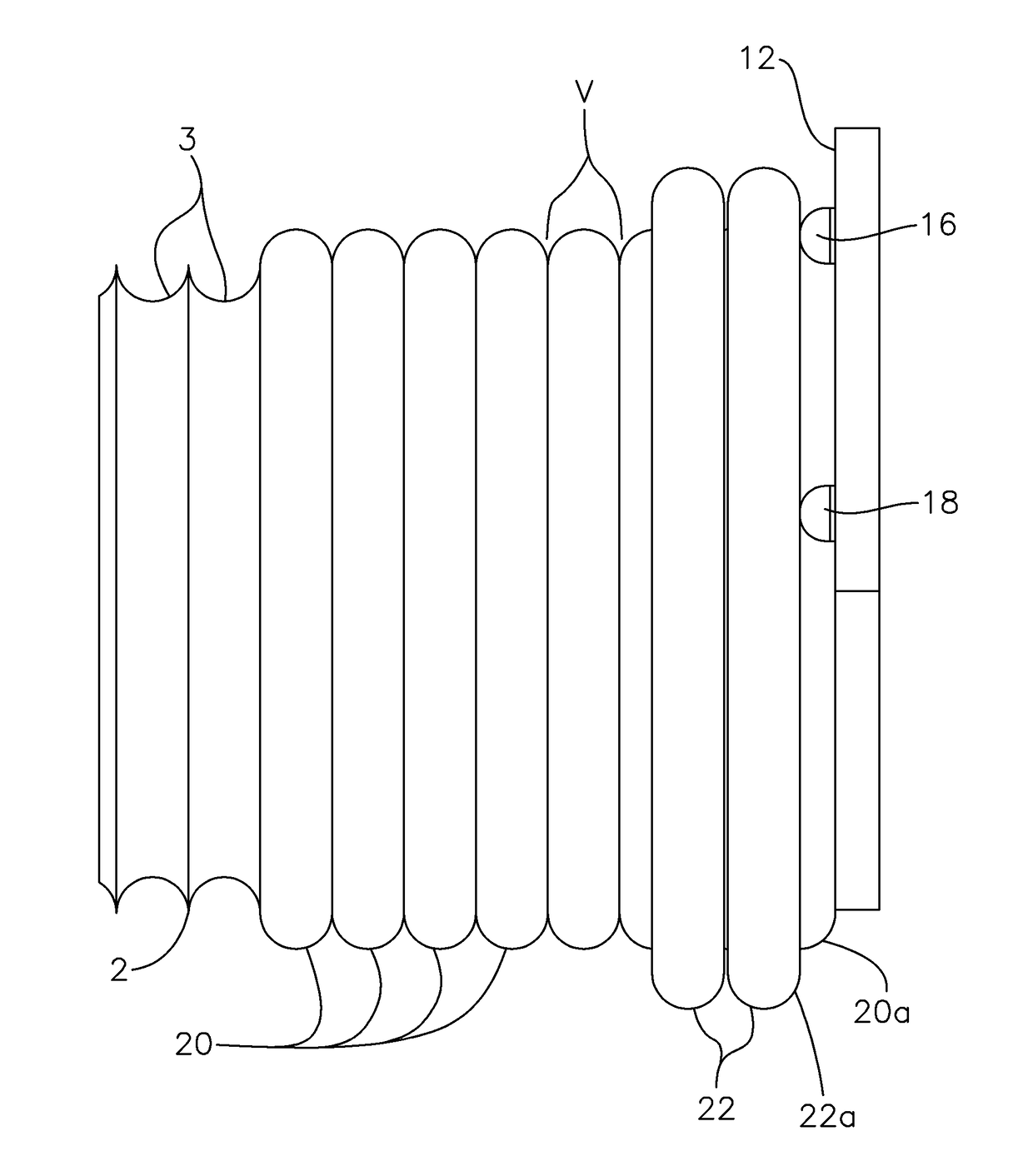
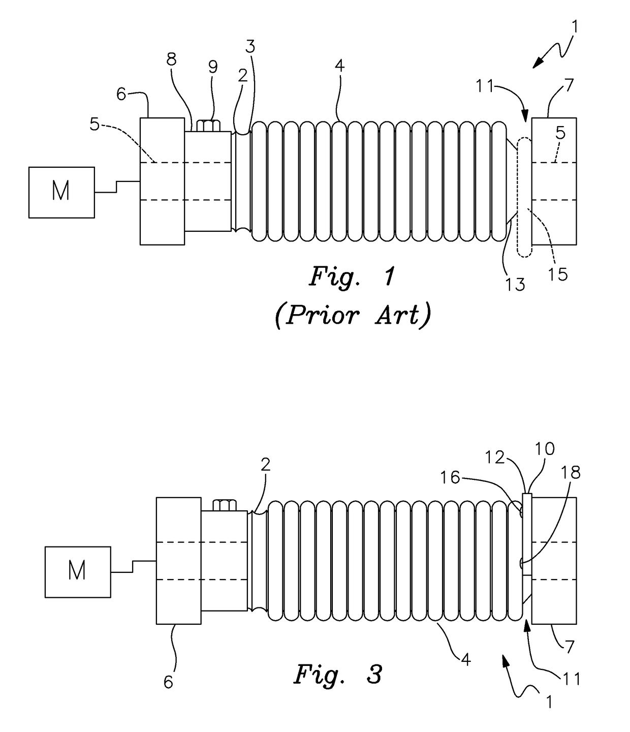
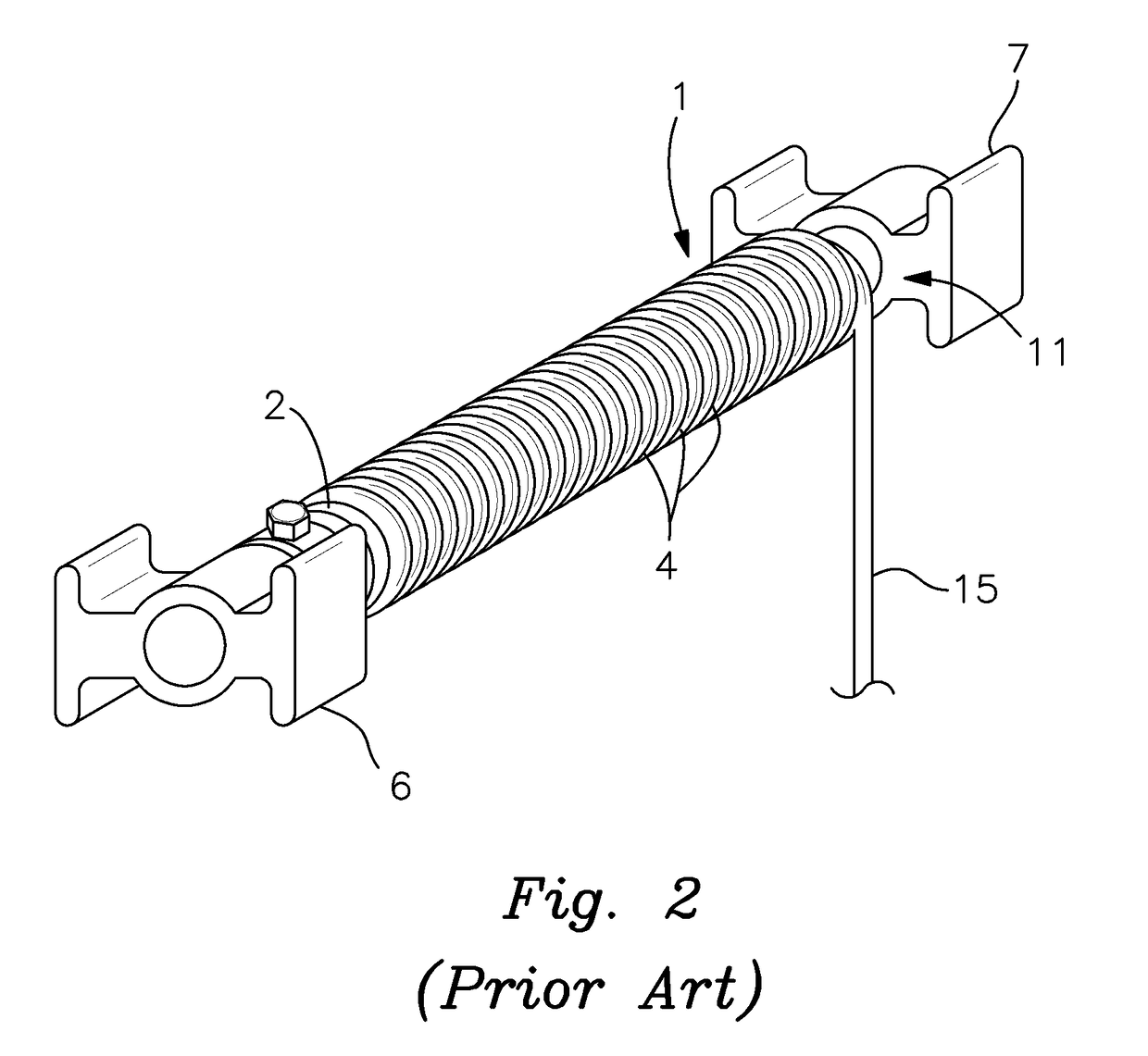
[0020]There is shown in FIGS. 1 and 2 a conventional winder mechanism 1 of the type commonly utilized in boat lifts and other lift applications. It should be understood that winder mechanism 1 is simplified somewhat in the drawings, but the construction and operation of the winder mechanism should be well understood by persons skilled in the art. Although the cable guard of this invention is particularly intended for use in boat lift winders, that should not be construed as a limitation on this invention as the disclosed invention may be used in other lift applications wherein a winch or winder drum, reel, spool or other winding component is driven to selectively wind a cable onto or unwind a cable from the circumferential surface of the winder. Although the term winder “drum” is used herein, it should be understood as referring to any and all generally cylindrical components, e.g. reels, spools, winches, etc. that are axially rotated to selectively wind and unwind elongate lifting ...


PUM


Abstract

A winder cable guard includes a generally flat plate that is attached to an inwardly facing surface of the outer support bearing in a winder mechanism. The plate is sized and configured to fit within and seal the clearance gap between the outer end of the winder drum and the outer support bearing. This prevents a cable being wound onto the winder drum from slipping or falling into the gap. The potential for jamming and/or breakage of the lift cable is thereby reduced.

Description

RELATED APPLICATION[0001]This application claims the benefit of U.S. Provisional Patent Application Ser. No. 62 / 251,216 filed Nov. 5, 2015.FIELD OF THE INVENTION[0002]This invention relates to a winder cable guard and, more particularly, to a guard or stop device that prevents a section of cable wound on a winder drum from falling or slipping into the gap that is typically formed between an outer end of the winder and an adjacent supportive bearing. The device is particularly effective for use in winders employed in boat lifts.BACKGROUND OF THE INVENTION[0003]Cable winders are commonly utilized in the boat lift industry as well as other lifting applications. Typically, such winders include an elongate drum or reel that is mounted on an axially rotatable, motor driven shaft. The shaft is, in turn, rotatably supported by a pair of bearings located proximate respective ends of the shaft. The winder drum typically includes a grooved circumferential surface on which the lifting cable is ...

Claims


Application Information

Patent Timeline
Patent Type & Authority Applications(United States)
IPC IPC(8): B65H57/02B65H75/26
CPCB65H75/265B65H57/02B63B21/16B66D1/28B66D1/36B66D1/38B65H75/26B66D1/00
Inventor GOLDEN, WILLIAM
Owner GOLDEN WILLIAM
Why Eureka
Try Eureka