Signal equalizer in a coherent optical receiver

a technology of optical receiver and equalizer, applied in the field of high-speed optical communication networks, can solve the problems of increasing the amount of distortion compensation that is required in order to obtain the same signal reach, the cost of increasing the size and/or complexity of the dispersion and polarization compensation blocks, and the inability to meet the increase in distortion compensation

Active Publication Date: 2011-08-23
CIENA
View PDF7 Cites 41 Cited by
  • Summary
  • Abstract
  • Description
  • Claims
  • Application Information

AI Technical Summary

Problems solved by technology

However, as the symbol rate is increased, the amount of distortion compensation that is required in order to obtain the same signal reach also increases.
These increases in distortion compensation can be met, using the system described above, but at a cost of increased size and / or complexity of the dispersion and polarization compensation blocks.

Method used


Image

  • Signal equalizer in a coherent optical receiver
  • Signal equalizer in a coherent optical receiver
  • Signal equalizer in a coherent optical receiver

Examples


Embodiment Construction

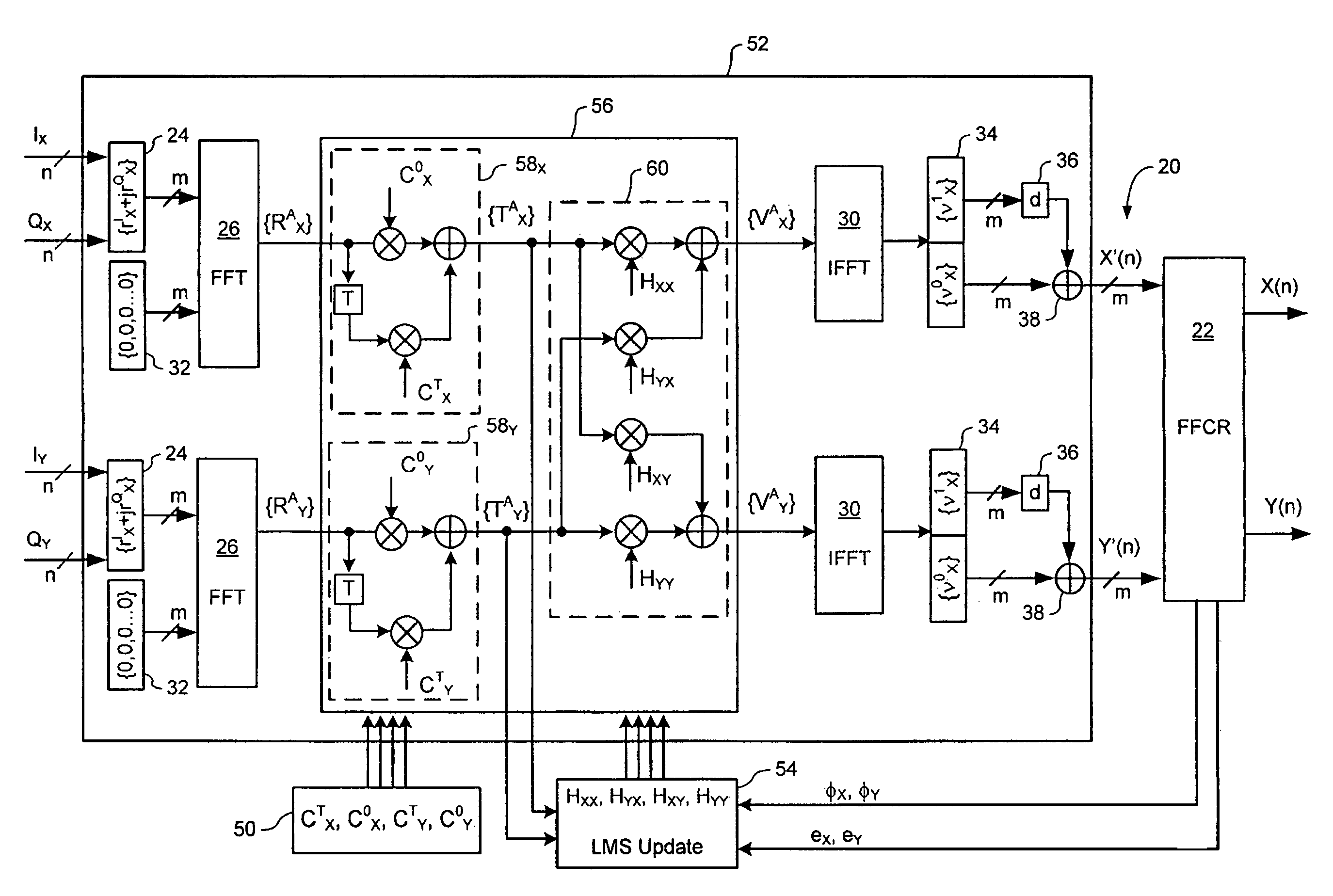
[0034]The present invention provides an agile signal equalizer for compensating dispersion and polarization impairments in a coherent optical receiver of a high speed optical network. Embodiments of the present invention are described below, by way of example only, with reference to FIGS. 3-7.

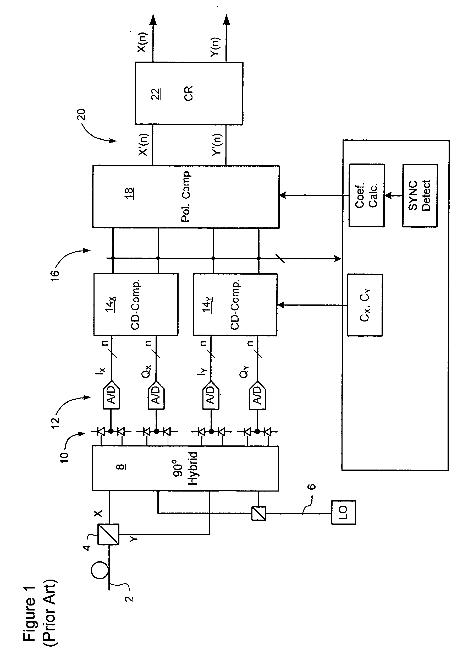
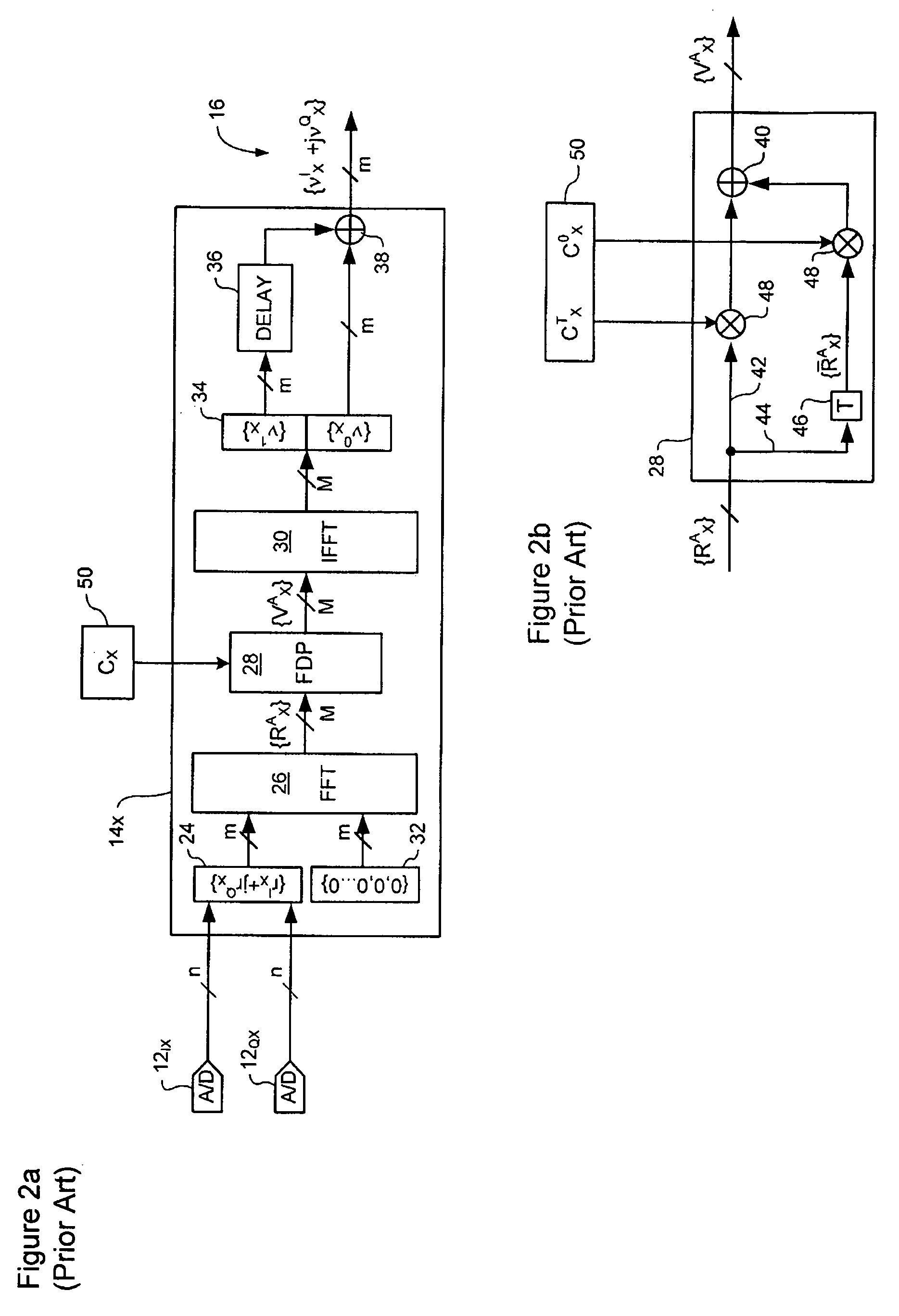
[0035]FIG. 3 illustrates principle elements of a coherent optical receiver which incorporates an agile signal equalizer 52 in accordance with the present invention. As may be seen in FIG. 3, the agile signal equalizer 52 combines the functionality of the dispersion compensation and polarization compensation blocks 14 and 18 of the system of FIG. 1. Thus, the agile signal equalizer 52 is capable of correcting timing errors between I and Q sample streams of each received polarization, compensating moderate to severe chromatic dispersion, and compensating polarization effects to thereby de-convolve symbols modulated onto each of the transmitted polarizations from the received signals.

[0036]As desc...


PUM


Abstract

A signal equalizer for compensating impairments of an optical signal received through a link of a high speed optical communications network. At least one set of compensation vectors are computed for compensating at least two distinct types of impairments. A frequency domain processor is coupled to receive respective raw multi-bit in-phase (I) and quadrature (Q) sample streams of each received polarization of the optical signal. The frequency domain processor operates to digitally process the multi-bit sample streams, using the compensation vectors, to generate multi-bit estimates of symbols modulated onto each transmitted polarization of the optical signal. The frequency domain processor exhibits respective different responses to each one of the at least two distinct types of impairments.

Description

CROSS-REFERENCE TO RELATED APPLICATIONS[0001]This is the first application filed in respect of the present invention.TECHNICAL FIELD[0002]The present invention relates to high-speed optical communications networks, and in particular to a signal equalizer in a coherent optical receiver.BACKGROUND OF THE INVENTION[0003]Optical signals received through conventional optical links are typically distorted by significant amounts of chromatic dispersion (CD) and polarization dependent impairments such as Polarization Mode Dispersion (PMD), polarization angle changes and polarization dependent loss (PDL). Chromatic dispersion (CD) on the order of 30,000 ps / nm, and polarization rotation transients at rates of 105 Hz are commonly encountered. Various methods and systems intended to address some of these limitations are known in the art.[0004]FIG. 1 schematically illustrates a representative coherent optical receiver capable of implementing the methods of Applicant's co-pending U.S. patent appl...

Claims


Application Information

Patent Timeline
Patent Type & Authority Patents(United States)
IPC IPC(8): H04B10/00
CPCH04B10/677H04B10/2572H04B10/6971H04B10/2569H04B10/532
Inventor ROBERTS, KIMSUN, HAN
Owner CIENA
Why Eureka
Try Eureka