
Systems and methods for computing a variogram model

a variogram and model technology, applied in the field of computing a variogram model, can solve the problems of considerable trial and error, poor linear best-fit in most rigorous cases, and the domain expertise of the user for the computation and fitting of a traditional semi-variogram,

Inactive Publication Date: 2011-08-30
LANDMARK GRAPHICS CORP
View PDF4 Cites 2 Cited by
  • Summary
  • Abstract
  • Description
  • Claims
  • Application Information

AI Technical Summary

Benefits of technology

The present invention provides systems and methods for computing a variogram model, which uses a variogram map and a rose diagram to compute the semi-variograms. This allows for more accurate and efficient analysis of data. The invention also includes a method for displaying the variogram map and rose diagram, and a data structure for storing the information needed for the analysis. The technical effects of the invention include improved accuracy and efficiency in analyzing data, as well as improved user experience in using the system.

Problems solved by technology

Finding a variogram model is one of most important and often difficult tasks in geostatistics / property modeling as it identifies the maximum and minimum directions of continuity of a given geologic or petrophysical property or any spatially correlated property.
Conventional methods for the computation and fitting of a traditional semi-variogram often require domain expertise on the part of the user and considerable trial and error.
The linear best-fit shown in FIG. 2, however, is not very good for most rigorous cases.
An approach is blind to the user when the user cannot give any input to the fit achieved by the automated function.

Method used


Image

  • Systems and methods for computing a variogram model
  • Systems and methods for computing a variogram model
  • Systems and methods for computing a variogram model

Examples


Embodiment Construction

[0023]The subject matter of the present invention is described with specificity, however, the description itself is not intended to limit the scope of the invention. The subject matter thus, might also be embodied in other ways, to include different steps or combinations of steps similar to the ones described herein, in conjunction with other present or future technologies. Moreover, although the term “step” may be used herein to describe different elements of methods employed, the term should not be interpreted as implying any particular order among or between various steps herein disclosed unless otherwise expressly limited by the description to a particular order.

Method Description

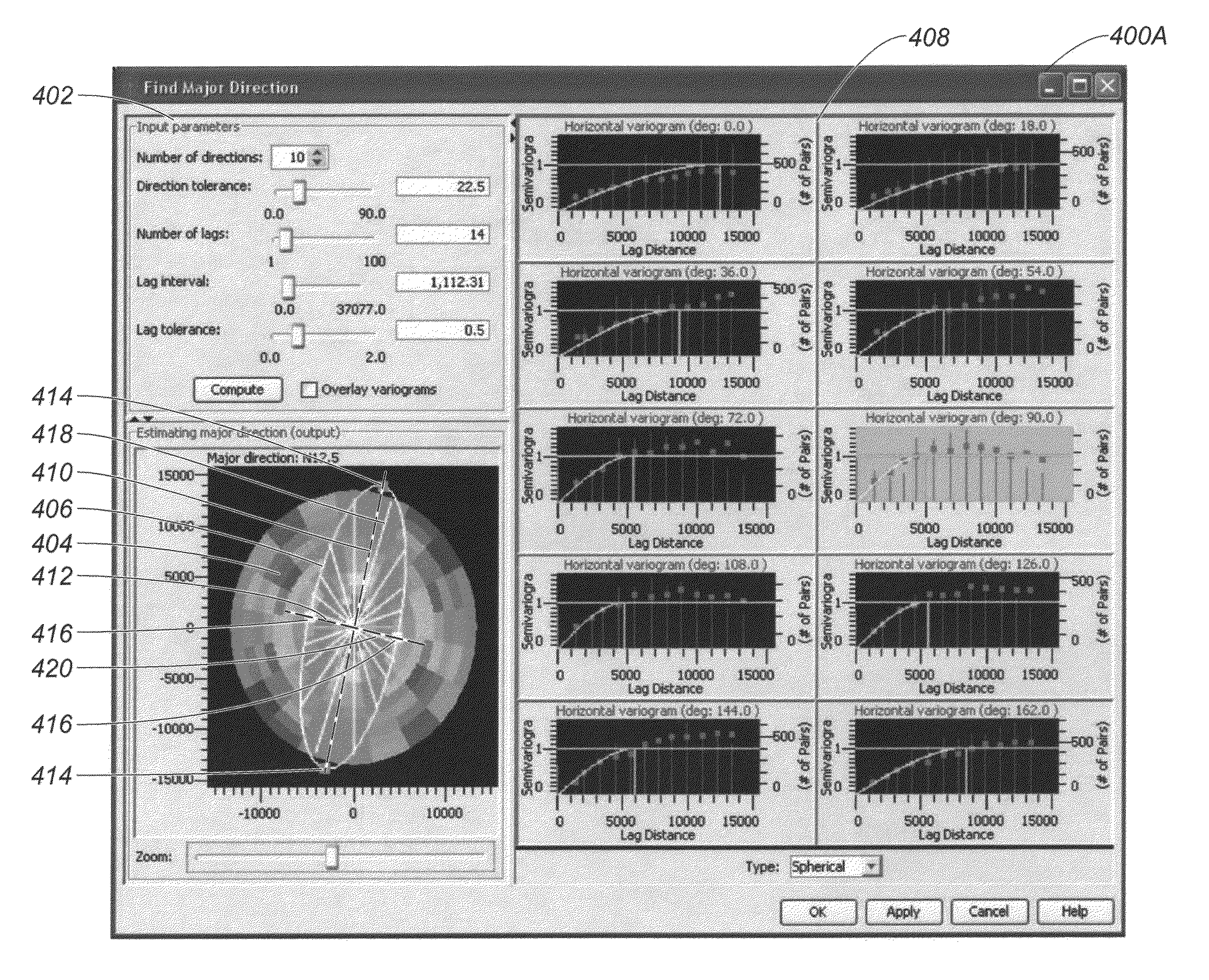
[0024]Referring now to FIG. 3, a flow diagram illustrates one embodiment of a method 300 for implementing the present invention.

[0025]In step 302, input parameters are selected using a graphical user interface and techniques well known in the art. The input parameters may be pre-selected as default sett...


PUM


Abstract

Systems and methods for computing a variogram model, which utilize a variogram map and a rose diagram to compute the model.

Description

CROSS-REFERENCE TO RELATED APPLICATIONS[0001]The priority of U.S. patent application No. 60 / 968,289, filed on Aug. 27, 2007, is hereby claimed, and the specification thereof is incorporated herein by reference. This application and U.S. patent application Ser. No. 12 / 605,945, which is incorporated herein by reference, are commonly assigned to Landmark Graphics Corporation.STATEMENT REGARDING FEDERALLY SPONSORED RESEARCH[0002]Not applicable.FIELD OF THE INVENTION[0003]The present invention generally relates to computing a variogram model for geostatistics / property modeling.BACKGROUND OF THE INVENTION[0004]Finding a variogram model is one of most important and often difficult tasks in geostatistics / property modeling as it identifies the maximum and minimum directions of continuity of a given geologic or petrophysical property or any spatially correlated property. The “maximum direction of continuity” is the azimuth along which the variance of a given property changes the least. The “m...

Claims


Application Information

Patent Timeline
Patent Type & Authority Patents(United States)
IPC IPC(8): G06T11/20
CPCG06F17/18G01V2210/641G01V2210/665G01V1/307G01V1/301G01V20/00
Inventor SHI, GENBAOCHAMBERS, RICHARD L.YARUS, JEFFREY M.
Owner LANDMARK GRAPHICS CORP
Learn More