Casing mount for a cylindrical vial

a casing mount and cylindrical technology, applied in the field of leveling, can solve the problems of increasing the cost of level manufacturing, and reducing the clarity of the vial, so as to improve the casing mount, improve the quality of the casing mount, and improve the effect of the overall structur

Active Publication Date: 2011-09-06
MILWAUKEE ELECTRIC TOOL CORP
View PDF30 Cites 5 Cited by
  • Summary
  • Abstract
  • Description
  • Claims
  • Application Information

AI Technical Summary

Benefits of technology

[0010]Another object of this invention is to provide an improved casing mount for a cylindrical vial to provide a clear open view for easy reading of the vial.
[0011]Another object of the invention is to provide an improved casing mount for a cylindrical vial to provide lasting protection of the vial.
[0012]Still another object of the invention is to provide an improved casing mount for a cylindrical vial of a simple and clean construction.
[0013]Another object of the invention is to provide an improved casing mount for a cylindrical vial which facilitates easy and inexpensive assembly of a level.

Problems solved by technology

While such block vials provide good protection for the vial, manufacturing of such block vials involves complicated techniques, including complicated machining of the interiors of block-vial interiors which increases the cost of level manufacturing.
Since block vials typically have a substantially rectangular outer shape and are installed in a round opening within the frame of the level, the sides of such rectangular block interfere with light rays and reduce clarity in vial reading.
Further, the space between the rectangular vial sides and the edges of the level-frame openings tends to become foggy or collect dust which further decreases the vial clarity and detracts from the overall quality of the level.
However, such prior installations have multiple shortcomings which negatively effect the quality of the levels and visual characteristics of the vial.
This results in higher cost and problems with respect to vial appearance and overall level quality.
Such features create multiple light-interfering structures about the vial, and this degrades overall visibility of the vial itself.
This compromises visibility of the vial from one side.
In addition, installation of the open vial casing to the level frame allows a probability of contamination of the interior of the holder, which results in degrading the space around the vial and, over time, reducing reading clarity of the vial itself.
Thus, the case interior is prone to contamination during handling and installation.
Finally, such octagonal shape, which is critical for the vial casing of the Marth et al. patent, by its nature has multiple differently-angled surfaces which reflect and bend light rays, thus decreasing clarity of observation of the vial.

Method used


Image

  • Casing mount for a cylindrical vial
  • Casing mount for a cylindrical vial
  • Casing mount for a cylindrical vial

Examples


Embodiment Construction

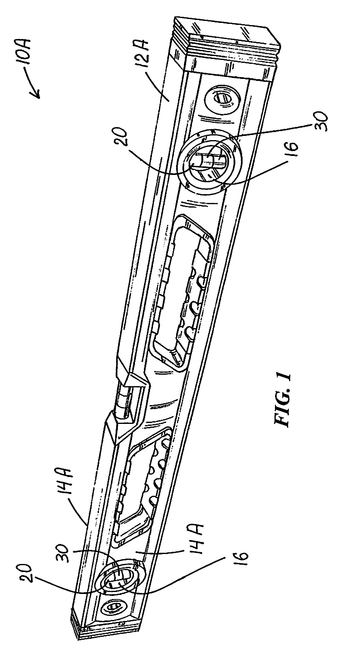
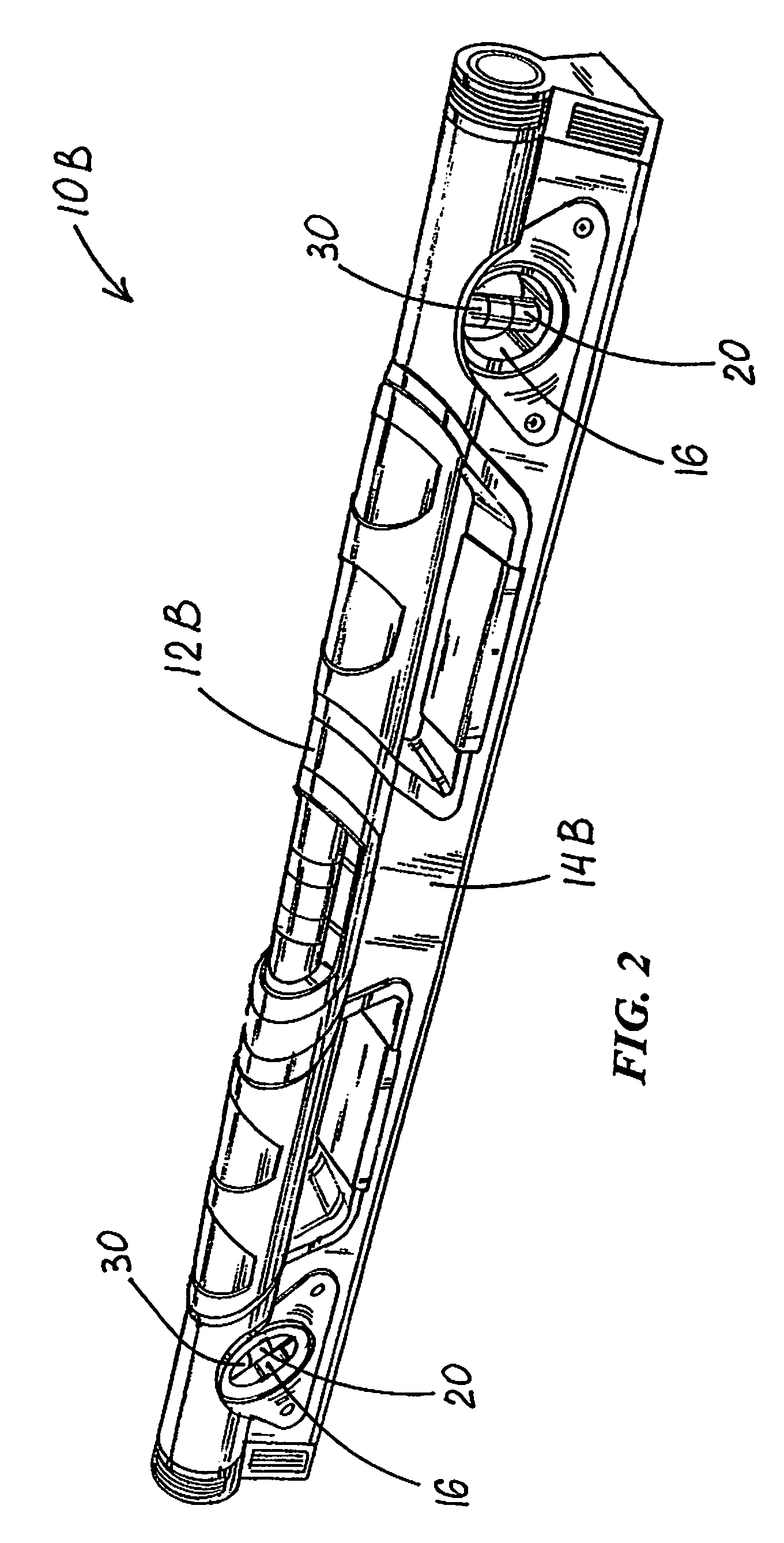
[0038]FIGS. 1 and 2 show levels 10A and 10B each including an elongate hollow frame 12 (A and B, respectively) formed by two sidewalls 14 (A and B, respectively) each defining axially aligned vial openings 16 into frame 12. Each of levels 10A and 10B has a liquid-and-bubble vial 20.

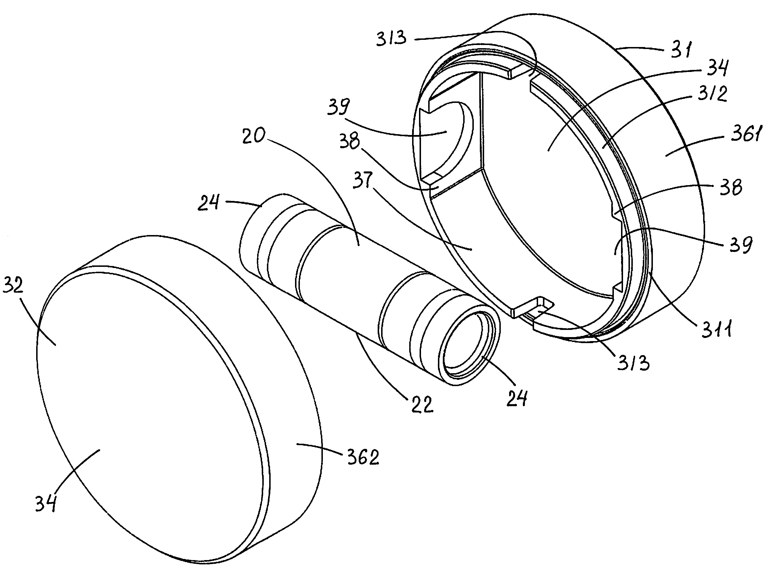
[0039]FIGS. 3-8 best illustrate a vial casing 30, which is secured with respect to frame 12. Casing 30 defines a hermetically sealed single-cavity casing interior 33 entirely enclosing vial 20. Vial 20 has a substantially cylindrical outer surface 22 extending between two vial ends 24. Casing 30 is formed of two opposite round face-walls 34 and a surrounding cylindrical wall 36 therebetween. It is best seen in FIGS. 3 and 6-8 that surrounding cylindrical wall 36 has a pair of opposed major wall-portions 37 of first thickness 37A and a pair of opposed intervening wall-portions 38 of second thickness 38A. Second thickness 38A is greater than first thickness 37A. Each intervening wall-portion 38 defines a re...


PUM


Abstract

A level of the type having an elongate hollow frame including two sidewalls each defining axially aligned vial openings into the frame. A vial casing is secured with respect to the frame and defines a hermetically sealed single-cavity casing interior entirely enclosing a liquid-and-bubble vial with a substantially cylindrical outer surface extending between two vial ends. The casing is formed of two opposite round face-walls and a surrounding cylindrical wall therebetween. The cylindrical wall has a pair of opposed major wall-portions of first thickness and a pair of opposed intervening wall-portions of second thickness greater than the first thickness. Each intervening wall-portion defines a recess which snugly receives a corresponding one of the vial ends. The inner surface of the surrounding wall is smooth and substantially free of light-ray-interfering structures, whereby the vial appears embedded in the surrounding wall and the face-walls provide uninterrupted full views of and about the cylindrical vial.

Description

FIELD OF THE INVENTION[0001]This invention relates to levels and, more particularly, to a vial assemblies for inclusion in levels.BACKGROUND OF THE INVENTION[0002]In the construction industry, levels are used to ensure that structural members are installed in their exact intended orientations. Common construction levels include plural vials to indicate at least horizontal and plumb (vertical) orientations. In addition to a centrally-positioned vial, most levels include at least one other vial positioned within the frame of the level away from the center. Because such other vial(s) can be viewed only from either side of the frame, it is desirable to provide a clear and open view of the vial which provides easy reading thereof.[0003]A number of prior levels have so-called block vials installed at within-the-frame positions such that they are viewable from the side of the frame. While such block vials provide good protection for the vial, manufacturing of such block vials involves comp...

Claims


Application Information

Patent Timeline
Patent Type & Authority Patents(United States)
IPC IPC(8): G01C9/00
CPCG01C9/28
Inventor CHRISTIANSON, JOHNSTANFORD, ROGER D.
Owner MILWAUKEE ELECTRIC TOOL CORP
Why Eureka
Try Eureka