Apparatus and method for prophylactic hip fixation

a hip and prophylactic technology, applied in the field of hip prophylactic fixation, can solve the problems that the bone is not generally prevented from initially fracturing, and achieve the effect of increasing the likelihood of the patien

Inactive Publication Date: 2011-09-06
ZIMMER INC
View PDF86 Cites 19 Cited by
  • Summary
  • Abstract
  • Description
  • Claims
  • Application Information

AI Technical Summary

Benefits of technology

[0011]Advantageously, the embodiments of the present invention may be used prophylactically by being inserted within the proximal femur prior to a fracture of the femoral neck and / or other severe damage of the proximal femur. In this manner, use of the present invention may provide rigidity and strength to the proximal femur. As a result, fracture of the femoral neck and / or other severe damage to the proximal femur may be prevented. For example, if a patient has suffered a fractured femoral neck on the left side of the patient's body, the present invention may be used prophylactically on the right side of the patient's body to prevent and / or lessen the potential for the femoral neck on the right side of the patient's body from suffering a similar fracture. Additionally, the present invention may be used in an individual diagnosed as being at high risk of suffering a femoral fracture, such as an individual diagnosed with osteoporosis.
[0015]In yet another form thereof, the present invention provides a method of prophylactic treatment of a proximal femur, the method including the steps of identifying that a patient has one of a disease and an aliment that increases the likelihood of the patient experiencing a fracture of one of a medial proximal femur and a lateral proximal femur and implanting an apparatus in at least one of the medial proximal femur and the lateral proximal femur to strength and support the at least one of the medial proximal femur and the lateral proximal femur prior to a fracture developing in the at least one of the medial proximal femur and the lateral proximal femur.

Problems solved by technology

Thus, these types of components are helpful in healing a damaged bone but may not generally prevent the bone from initially fracturing.

Method used


Image

  • Apparatus and method for prophylactic hip fixation
  • Apparatus and method for prophylactic hip fixation
  • Apparatus and method for prophylactic hip fixation

Examples


Embodiment Construction

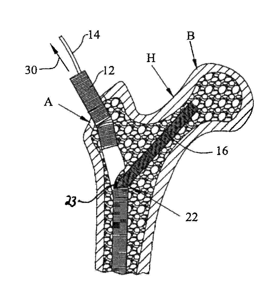
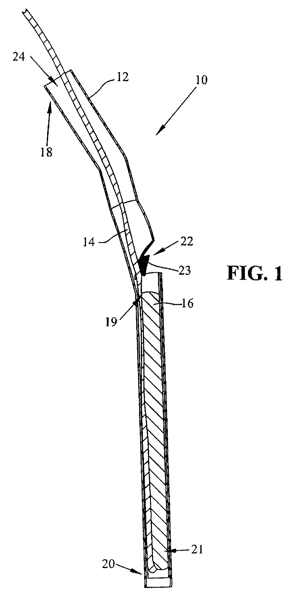
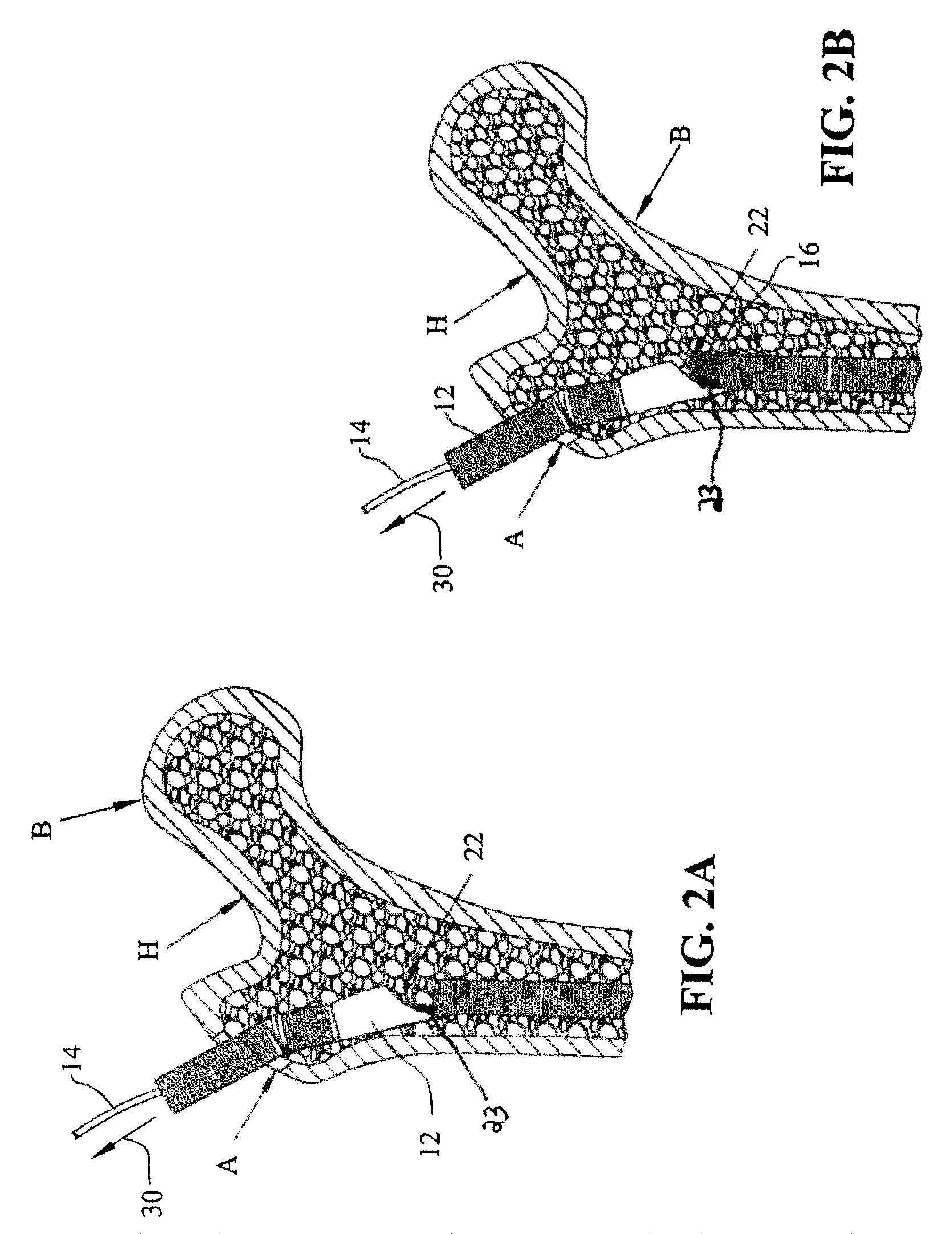
[0036]FIG. 1 is a sectional view of an apparatus representing an embodiment of the present invention, generally indicated by numeral 10. Apparatus 10 includes a housing 12, a cable 14 and a support member 16. In the depicted embodiment, housing 12 has a substantially circular cross section and includes a proximal end 18 and a distal end 20. Housing 12 is substantially hollow and includes an opening 22 formed in the side of the housing 12. Housing 12 also includes an opening 24 formed in the proximal end 18.

[0037]Support member 16 includes a proximal end 19 and a distal end 21. The cable 14 is connected to the support member 16 in a manner ensuring that the movement of cable 14 translates into movement of the support member 16. For example, the cable 14 may be connected to the support member 16 at least near the distal end 21 of the support member 16.

[0038]In the depicted embodiment, the support member 16 is at least partially flexible. In addition, the support member 16 is sized so ...


PUM


Abstract

A method and apparatus configured to strengthen and support a portion of a bone, such as the femoral head of the proximal femur, for example. The apparatus may include a housing or base member and a movable support member connected to the housing and configured to move between a first, undeployed position in which the support member is disposed proximate the housing or base such that the apparatus may be inserted into bone, and a second, deployed position in which the support member extends away from the housing or base for supporting the femoral head. The support member may be a rod, one or more wires, a leaf spring, a bladder, or an expandable mesh material, for example.

Description

BACKGROUND[0001]1. Field of the Invention[0002]The present invention relates to an apparatus and method for supporting and / or stabilizing a bone structure, such as the femoral head of the proximal femur.[0003]2. Description of the Related Art[0004]In general, known techniques for treating weakened bone structure in the proximal femur involve the use of intramedullary nails or bone plates and bone screws configured to provide a mechanism for stabilizing the bone. These devices are typically utilized after the bone has fractured in order to facilitate the healing of the fracture. Thus, these types of components are helpful in healing a damaged bone but may not generally prevent the bone from initially fracturing.[0005]The replacement of damaged or weakened hips is also known. For example, U.S. Pat. No. 7,044,978 is hereby incorporated herein in its entirety by reference and discloses a positioner and method for a femoral hip implant. The disclosed hip implant is configured to replace ...

Claims


Application Information

Patent Timeline
Patent Type & Authority Patents(United States)
IPC IPC(8): A61B17/56
CPCA61B17/7208A61B17/7258A61B17/744A61B2017/00867
Inventor PRYGOSKI, MATTHEW P.LOZIER, ANTONY J.PARROTT, RUSSELL M.GRAY, ANDREW L.PACELLI, NICOLAS J.
Owner ZIMMER INC
Why Eureka
Try Eureka