
Portable chair

a chair and portability technology, applied in the field of portable chairs, can solve the problems of weak structure of the frame intersection portion, difficult to carry the chair, and long sitting time of the user, and achieve the effect of strengthening the strength

Active Publication Date: 2012-05-03
LAH JEH KUN
View PDF5 Cites 49 Cited by
  • Summary
  • Abstract
  • Description
  • Claims
  • Application Information

AI Technical Summary

Benefits of technology

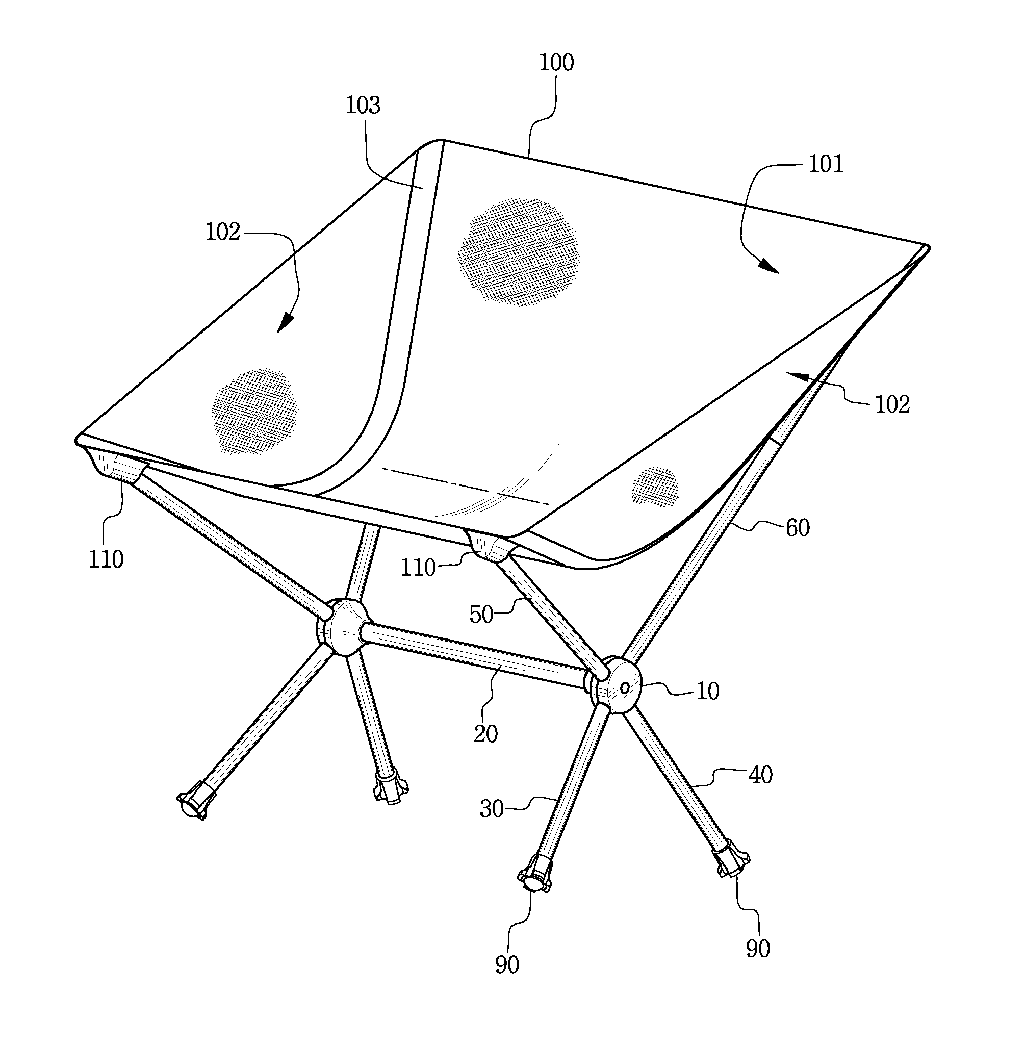
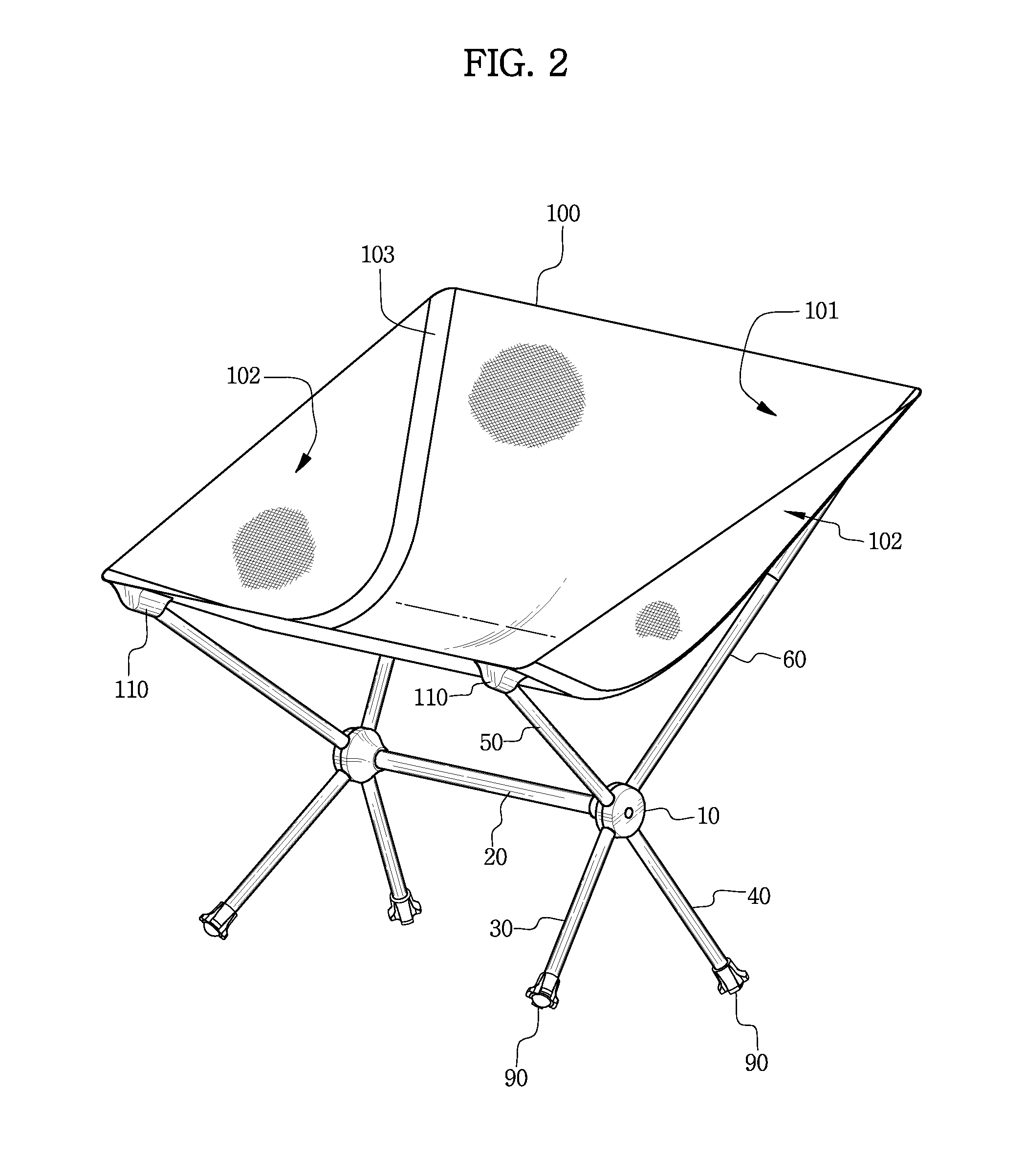
"The present disclosure is about a portable chair that improves the strength of existing portable chairs and solves their weaknesses. The chair is easy to fold and unfold, has excellent support rigidity, and minimizes structural weaknesses by using a frame structure. It also helps users feel comfortable for a long period of time by wrapping the left and right sides of the butt and the front and rear pole frames. Additionally, the chair stably lands on uneven ground surfaces by providing a rotatable hub and elastic strings. The chair includes hubs, frames, and a fabric sheet connected to the frames. The fabric sheet wraps the user's butt, thigh, and waist and has a curved seating surface and blocking side surfaces."

Problems solved by technology

However, since the fabric sheet is small and flat, it is difficult for the user to sit thereon for a long period of time due to low comfortability.
Furthermore, since the chair has a structure in which the intersection of the frames receiving the concentrated load is perforated and a hinge pin is inserted thereinto, the frame intersection portion is weak in structure.
However, it is difficult to carry the chair since the volume of the folded chair is large, and it is difficult to use the chair in the outdoor place when the ground surface is wet or uneven since the chair has no leg.
However, it is difficult to carry the chair since the volume of the folded chair is large, and the structure becomes complicated in that the hinge structure may be employed for many points.
In addition, there is a concern that the chair is not comfortably operated or is not operated at the time of using the chair at the outdoor place when foreign matters intrude into the hinge portions.

Method used


Image

  • Portable chair
  • Portable chair
  • Portable chair

Examples


Embodiment Construction

[0038]Exemplary embodiments now will be described more fully hereinafter with reference to the accompanying drawings, in which exemplary embodiments are shown. The present disclosure may, however, be embodied in many different forms and should not be construed as limited to the exemplary embodiments set forth therein. Rather, these exemplary embodiments are provided so that the present disclosure will be thorough and complete, and will fully convey the scope of the present disclosure to those skilled in the art. In the description, details of well-known features and techniques may be omitted to avoid unnecessarily obscuring the presented embodiments.

[0039]The terminology used herein is for the purpose of describing particular embodiments only and is not intended to be limiting of the present disclosure. As used herein, the singular forms “a”, “an” and “the” are intended to include the plural forms as well, unless the context clearly indicates otherwise. Furthermore, the use of the t...


PUM


Abstract

The portable chair of the disclosure includes: hubs respectively installed at both left and right sides of the chair; a central support frame connecting both left and right hubs; front and rear leg frames respectively having base ends separably coupled to the lower front and rear outer peripheral surfaces of the respective hubs and respectively having free ends disposed in a manner of radially extending toward the ground surface; front and rear pole frames respectively having base ends separably coupled to the upper front and rear outer peripheral surfaces of the respective hubs and respectively having free ends disposed in a manner of radially extending toward the sky; and a fabric sheet coupled to the free ends of the front and rear pole frames. The structural rigidity is excellent, and the chair may land on the ground surface in a stable posture.

Description

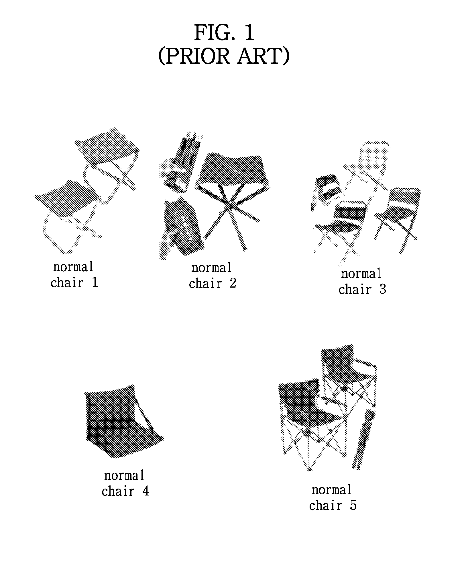
CROSS-REFERENCE TO RELATED APPLICATION[0001]This application claims priority to Korean Patent Application No. 10-2010-0105917, filed on Oct. 28, 2010, and all the benefits accruing therefrom under 35 U.S.C. §119, the contents of which in its entirety are herein incorporated by reference.BACKGROUND[0002]1. Field[0003]The present disclosure relates to a portable chair, and more particularly, to a portable chair which is easily folded and unfolded, has a small volume, and improves stability and comfortability.[0004]2. Description of the Related Art[0005]A portable chair has been provided in various forms such as a foldable chair, a chair with a back support portion, a chair without a back support portion, and the like in accordance with the types or the purposes of outdoor activities such as camping or fishing.[0006]Various kinds of examples of the related art concerned with the portable chair are shown in FIG. 1 which is one of the accompanied drawings.[0007]Among the portable chairs ...

Claims


Application Information

Patent Timeline
Patent Type & Authority Applications(United States)
IPC IPC(8): A47C4/28
CPCA47C4/286A47C9/105A47C4/02
Inventor LAH, JEH-KUN
Owner LAH JEH KUN
Learn More