Golf club head

Inactive Publication Date: 2008-02-07
FUSHENG IND CO LTD
View PDF14 Cites 52 Cited by
  • Summary
  • Abstract
  • Description
  • Claims
  • Application Information

AI Technical Summary

Benefits of technology

[0008]Accordingly, one objective of the present invention is to provide a golf club head, in which

Problems solved by technology

However, the COR region of the striking plate with uniform thickness is usually in the central region of the striking plate, and the durability of the striking plate is degraded as

Method used


Image

  • Golf club head
  • Golf club head
  • Golf club head

Examples


Example

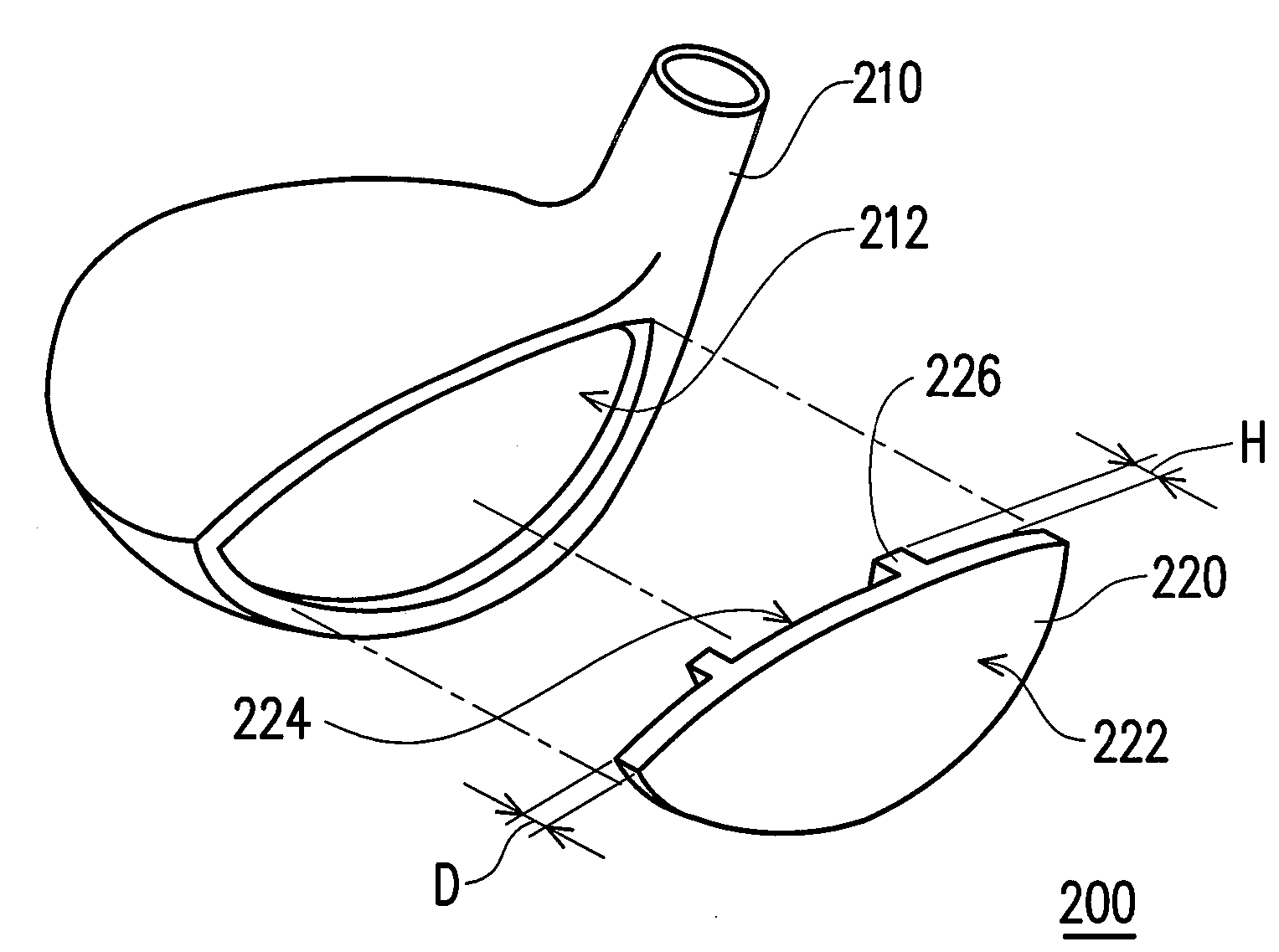
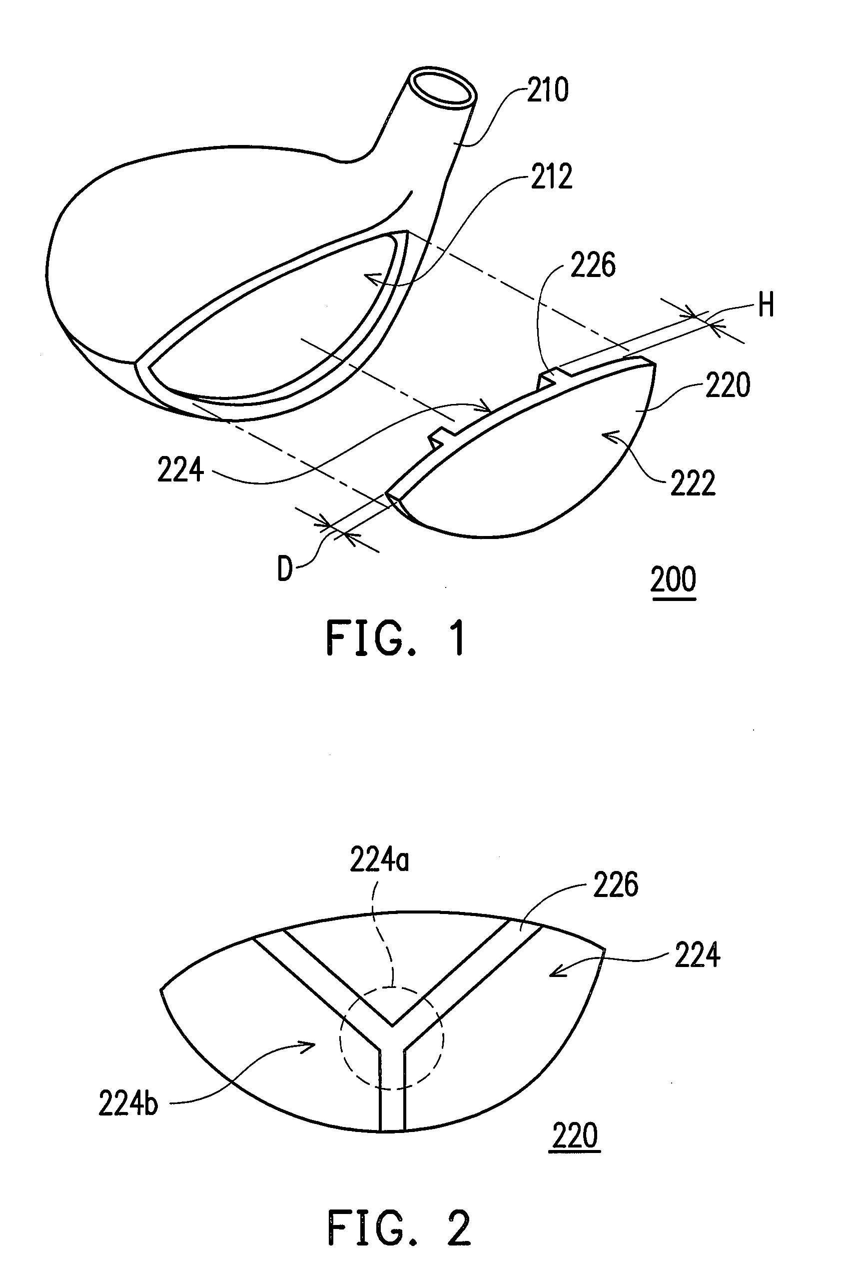
[0017]Referring to FIGS. 1 and 2, FIG. 1 is a schematic exploded stereo view of the golf club head according to an embodiment of the present invention and FIG. 2 is a schematic rear view of the striking plate in FIG. 1. The golf club head 200 of the present embodiment comprises a body 210 and a striking plate 220. The body 210 has an opening 212. In the present embodiment, the body 210 is a shell made of a common metal material (such as stainless steel) and being integrally formed by means of lost-wax casting.

[0018]Definitely, in other embodiments of the present invention, the body 210 can also made of composite material of metal and high molecular plastic material or high strength fiber material (such as carbon fiber). A manufacturing process of the body 210 includes the following steps. A crown (not shown) is first independently manufactured by means of, for example, injection molding or thermal compression molding, and then embedded into other portions of the metal shell. Further...


PUM


Abstract

A golf club head including a body and a striking plate is provided. The body has an opening. The striking plate is disposed at the opening. The striking plate integrally formed has a striking surface exposed to the outside, a non-striking surface opposite to the striking surface, and multiple ribs spread on the non-striking surface. The thickness of the striking plate is between 1.5-4 mm. The thickness of each rib is between 0.1-3.5 mm. The ribs intersect in the region of which the center of a circle is the geometric center of the non-striking surface and of which the diameter is 20 mm.

Description

CROSS-REFERENCE TO RELATED APPLICATION[0001]This application claims the priority benefit of Taiwan application serial no. 95213718, filed Aug. 4, 2006. All disclosure of the Taiwan application is incorporated herein by reference.BACKGROUND OF THE INVENTION[0002]1. Field of Invention[0003]The present invention relates to a golf club head. More particularly, the present invention relates to a golf club head with a striking plate having a plurality of ribs.[0004]2. Description of Related Art[0005]With the popularity of sports in today's society, golf has become one of the favorite sports widely accepted by the masses, and more and more people participate in the golf sports, wherein golf clubs can be classified into wooden clubs, iron clubs, putters, and so on according to various fields and usage.[0006]As for the wooden club, a golf club head is usually fabricated by a body made of a metal material or carbon fiber and a striking plate integrated with the body as a whole for striking a ...

Claims


Application Information

Patent Timeline
IPC IPC(8): A63B53/00A63B53/04A63B102/32
CPCA63B53/0466A63B2053/0408A63B2053/0416A63B2209/023A63B2053/0454A63B2053/0458A63B2053/045A63B53/0408A63B53/0416A63B53/045A63B53/0454A63B53/0458
Inventor LO, LAI-FA
Owner FUSHENG IND CO LTD
Why Eureka
Try Eureka