RF coaxial connector

a coaxial connector and coaxial cable technology, applied in the direction of coupling device connection, coupling device details, two-pole connection, etc., can solve the problem of high impedance of the region, and achieve the effect of enhancing the compensation effect and low impedance region

Active Publication Date: 2011-09-13
RADIALL SA
View PDF2 Cites 10 Cited by
  • Summary
  • Abstract
  • Description
  • Claims
  • Application Information

AI Technical Summary

Benefits of technology

[0027]The present invention may achieve following advantageous effects. When the dumbbell-shaped first insulating body is disposed inside the plug of the adapter, different impedance regions may be formed at the connection regions of the plug and the socket. If a large axial offset distance exists between the connecting elements, a large air gap may appear at the connection interface, thereby forming a high impedance region. Meanwhile, an end portion of the first insulating body may form a low impedance region and an annular gap between the middle portion of the first insulating body and the outer conductor of the adapter may form a normal impedance region. Because the high impedance region and the low impedance region may compensate each other, the adverse effect of the high impedance region to the connector performance may be decreased and the electrical and RF performance of the product may be improved. Therefore, compared with the prior art, the RF coaxial connector of the present invention may allow a larger axial offset (>1 mm), reduce the impedance mismatch caused by the air gap at the connection interface, and achieve preferred RF electrical performance over a frequency range from 0 to 6 GHz.
[0028]A low impedance region may also be formed at the shoulder portion region. Thus, the low impedance regions may be formed at both sides of the high impedance region, thereby enhancing the compensation effect.

Problems solved by technology

An air gap at the connection interface leads to high impedance of the region.

Method used


Image

  • RF coaxial connector
  • RF coaxial connector
  • RF coaxial connector

Examples


Embodiment Construction

[0037]The following illustrative embodiments are provided to illustrate the disclosure of the present invention, these and other advantages and effects may be apparent to those skilled in the art after reading the disclosure of this specification.

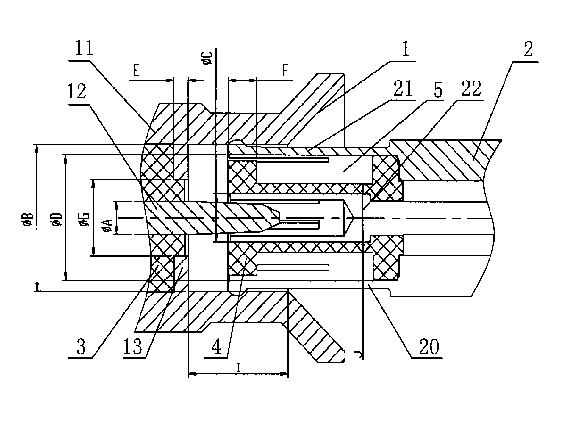
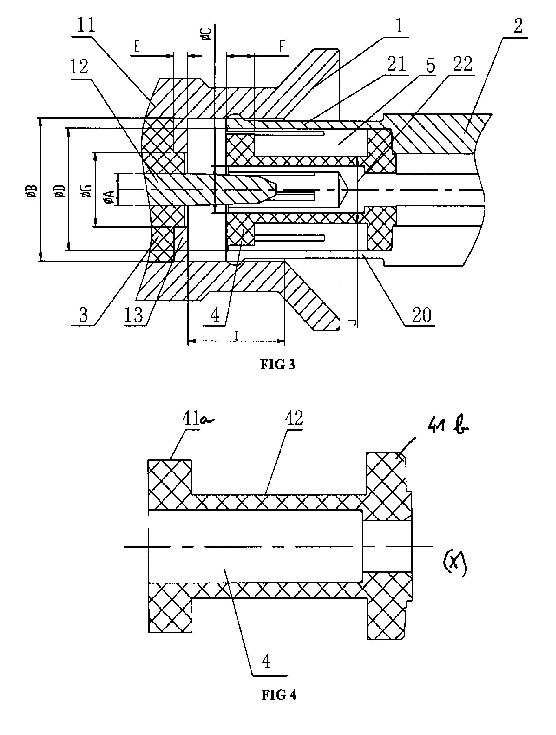
[0038]As shown in FIG. 3, a RF coaxial connector according to exemplary embodiments of the present invention comprises a socket 1 and an adapter 2. The socket 1 comprises an outer conductor 11 and a center conductor 12. The adapter 2 comprises a plug 20 disposed at one end thereof and capable of being inserted into the socket 1. The adapter 2 further comprises an outer conductor 21 and a center conductor 22. When the plug 20 is inserted into the socket 1, the outer conductor 21 and center conductor 22 of the adapter 2 are in contact with the outer conductor 11 and center conductor 12 of the socket 1, respectively.

[0039]A dumbbell-shaped first insulating body 4 extending along a longitudinal axis X is disposed inside the plug 20 of the adapt...


PUM


Abstract

The invention discloses a RF coaxial connector, which includes a socket and an adapter. The socket includes an outer conductor and a center conductor. The adapter includes a plug capable of being inserted into the socket. The adapter also includes an outer conductor and a center conductor that can be in contact with the outer conductor and the center conductor of the socket, respectively. A dumbbell-shaped first insulating body is disposed inside the plug of the adapter and filled between the outer conductor and the center conductor of the adapter. The first insulating body has a middle portion narrower than two end portions thereof such that an annular gap is formed between the middle portion of the first insulating body and the outer conductor of the adapter, thereby forming different impedance regions at the connection regions of the plug and the socket. Therefore, a high impedance region and a low impedance region can compensate each other so as to decrease the adverse effect of the high impedance region on the connector performance and improve electrical and RF performance of the product. Compared with the prior art, the connector of the present invention allows a larger axial offset.

Description

BACKGROUND OF THE INVENTION[0001]1. Field of the Invention[0002]The present invention relates to a RF coaxial connector.[0003]2. Description of Related Art[0004]RF coaxial connectors are used for providing interconnection between circuit boards, between RF modules, or between circuit boards and RF modules. In these applications, the allowable tolerance between relative positions of two connected elements tends to increase so as to facilitate fabrication of the elements and reduce the fabrication cost.[0005]Currently, there are several circuit board interconnection techniques that allow axial and radial offsets between circuit boards. The oldest technique is based on standard snap-on connectors, such as SMB and MCX connectors, which have sockets and plugs for interconnecting the circuit boards. As shown in FIG. 1, in such a connector, inner conductors and outer conductors thereof have a staggered pin and insertion hole arrangement, which allows a limited axial offset. Since the elast...

Claims


Application Information

Patent Timeline
Patent Type & Authority Patents(United States)
IPC IPC(8): H01R9/05H01R13/646
CPCH01R13/6315H01R24/44H01R24/50H01R2103/00
Inventor XIE, GUANGRONGBROCHETON, CLAUDE
Owner RADIALL SA
Why Eureka
Try Eureka