Image processing device

a processing device and image technology, applied in the field of image processing devices, can solve the problems of deteriorating image quality, unable to detect the area that is actually a low chroma area, and unable to sufficiently suppress false colors, so as to improve the detection accuracy of chroma, improve the performance of suppressing the occurrence of “color omission”, and improve the effect of high chroma region

Active Publication Date: 2011-07-28
EVIDENT CORP
View PDF8 Cites 11 Cited by
  • Summary
  • Abstract
  • Description
  • Claims
  • Application Information

AI Technical Summary

Benefits of technology

[0014]According to the present invention, it is possible to reproduce a further natural image by improving a detection accuracy of a chroma in a subject image, thereby suppressing a false color in a low chroma region and improving a performance of suppressing occurrence of “color omission” in a high chroma region, such that a false-color reduced color signal in which an effect of a false color is reduced is obtained from image signals of plural primary colors for respective pixels, and a chroma signal is generated for each of the pixels on the basis of the obtained false-color reduced color signal.

Problems solved by technology

However, according to the conventional technique, the color component signal used at the time of detecting the low chroma region already contains the false color, causing incorrect detection of the low chroma region, whereby the false color cannot be sufficiently suppressed at the low chrome region.
However, since these signals contain the false color component (R−B), an area that is actually a low chroma area cannot be detected as the low chroma area when a large amount of high frequency component is included in the image.
As a result, the false color is not suppressed sufficiently in the low chroma region where the false color is conspicuous, possibly deteriorating quality of the image.

Method used


Image

  • Image processing device
  • Image processing device
  • Image processing device

Examples


first embodiment

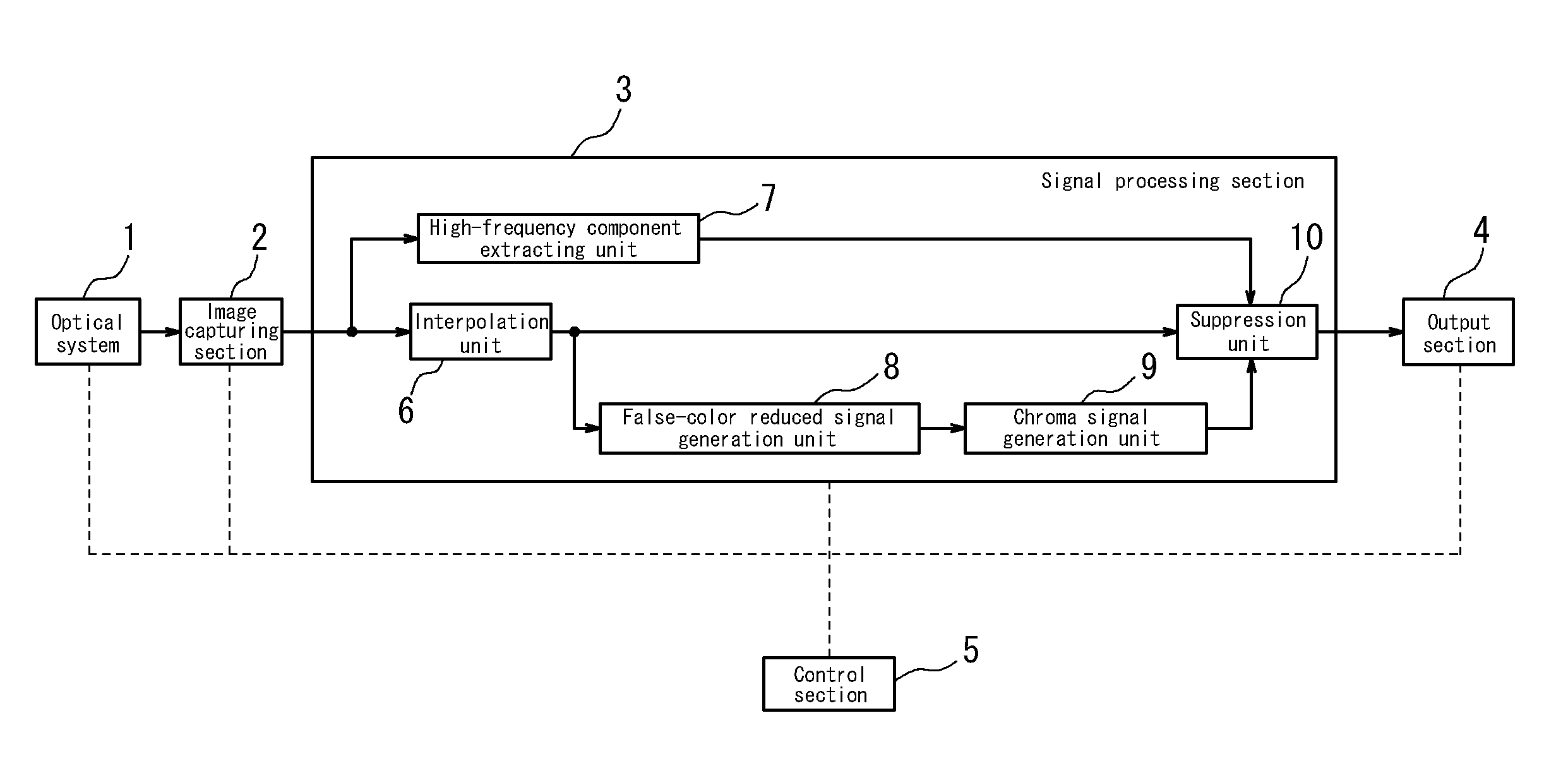
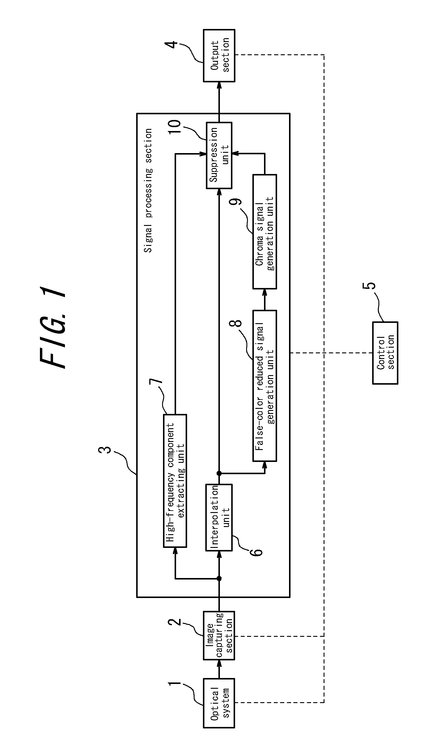
[0028]First, the first embodiment of an image processing device according to the present invention will be described. This embodiment is an example in which the image processing device according to the present invention is applied to a digital camera. FIG. 1 is a block diagram illustrating a schematic configuration of a digital camera having the image processing device according to the present invention. This embodiment has means for generating a color signal in which the false color is reduced and which is used at the time of detecting a low chroma region, and is characterized in that a process of reducing the false color is implemented to a color component signal in the detected low chroma region.

[0029]The digital camera in FIG. 1 includes an optical system 1, an image capturing section 2, a signal processing section 3 corresponding to the image processing device according to the present invention, an output section 4, and a control section 5. The optical system 1 includes an imag...

second embodiment

[0057]Next, the second embodiment of the image processing device according to the present invention will be described. In this embodiment, an image processing device similar to the image processing device according to the first embodiment is installed in a microscope. FIG. 8 illustrates a schematic configuration of a microscope according to the second embodiment of the present invention.

[0058]According to this embodiment, a microscope 200 includes a microscope body 201 having an illumination optical system, an observation optical system, a sample stage and the like; an image capturing section 202; a signal processing section 203; an output section 204; and a control section 205. Explanations of the image capturing section 202, the signal processing section 203, the output section 204 and the control section 205 are omitted because those have almost the same configurations and operations as the image capturing section 2, the signal processing section 3, the output section 4 and the c...

third embodiment

[0061]Next, the third embodiment of the image processing device according to the present invention will be described. This embodiment is configured that, in the digital camera according to the first embodiment, suppression of the false color by the signal processing section 3 is not implemented to image signals of the primary colors of the respective pixels, but those image signals are converted into image signals represented in another color space and the suppression of the false color is implemented to the converted image signals. FIG. 9 is a block diagram illustrating a schematic configuration of the digital camera according to this embodiment of the present invention.

[0062]According to this embodiment, the signal processing section 3 includes the interpolation unit 6, a color-space conversion unit 11, a high-frequency component extracting unit 7′, a false-color reduced color signal generation unit 8′, a chroma signal generation unit 9′ and a suppression unit 10′.

[0063]The color-...


PUM


Abstract

An image capturing element of an image capturing section 2 has a color filter with a Bayer matrix, and interpolation unit 6 implements an interpolation process to an image signal for each pixel received from the image capturing element by using image signals of adjacent pixels to obtain an image signal of R, G and B for the respective pixels. High-frequency component extracting unit 7 extracts a high frequency component from the G signal; false-color reduced color signal generation unit 8 obtains, for the respective pixels, a false-color reduced color signal (R+B−2G) in which an effect of a false color is reduced; and, chroma signal generation unit 9 generates a chroma signal, which is an absolute value of the false-color reduced color signal. Suppression unit 10 suppresses the false color on the basis of the high frequency component extracted by the high-frequency component extracting unit 7 and the chroma signal for the respective pixels generated by the chroma signal generation unit 9.

Description

CROSS-REFERENCE TO RELATED APPLICATION[0001]The present application claims priority from Japanese Application No. 2010-013370, filed on Jan. 25, 2010, the content of which is incorporated herein by reference.TECHNICAL FIELD[0002]The present invention relates to an image processing device for use in a digital camera, microscope or the like.BACKGROUND OF THE INVENTION[0003]Conventionally, a CCD (charge coupled device) has been widely used as an image capturing element for a digital camera or video camera. The CCD has a structure in which a large number of photoelectric conversion elements are arranged, for example, in a grid pattern. When receiving light, the photoelectric conversion elements generate electrical charges in accordance with an intensity of the light, and the generated electrical charges are read out sequentially, whereby an image of a subject can be converted into electrical signals.[0004]In order to obtain a color image using the CCD, a color filter containing plural p...

Claims


Application Information

Patent Timeline
Patent Type & Authority Applications(United States)
IPC IPC(8): H04N9/64
CPCH04N9/045H04N9/77H04N9/646H04N23/843H04N25/134
Inventor HORIE, GEN
Owner EVIDENT CORP
Why Eureka
Try Eureka