Tool having clamping chuck

a tool and chuck technology, applied in the field of tools including chucks, can solve the problems of adverse storage or packaging for the typical clamping chuck, and achieve the effect of quick and solid securing of tool bits

Inactive Publication Date: 2011-09-20
LIN HUNG WEI
View PDF24 Cites 7 Cited by
  • Summary
  • Abstract
  • Description
  • Claims
  • Application Information

AI Technical Summary

Benefits of technology

[0010]The primary objective of the present invention is to provide a chisel including a clamping chuck for replaceably or changeably attaching the tool bits or tool members and for quickly and solidly securing the tool bits or tool members to the chisel.
[0014]The control ferrule includes an inner peripheral recess formed in a front end portion thereof for forming the inner peripheral shoulder in the front end portion thereof and for engaging with the peripheral flange of the shank and for limiting the control ferrule to move relative to the shank and for preventing the control ferrule from being disengaged from the shank.
[0015]The shank includes a stop attached to the shank and engaged with the control ferrule for anchoring the control ferrule to the shank and for preventing the control ferrule from being rotated relative to the shank.
[0016]The control ferrule includes an inner peripheral channel formed in a rear end portion thereof for rotatably engaging with the stop and for rotatably anchoring the control ferrule to the shank and thus for preventing the control ferrule from being slid relative to the shank.

Problems solved by technology

However, the tip is solidly formed or provided or secured to the shank and may not be removed from the shank and also may not be changed to the other tips.
However, an enlarged block or apparatus is required to be formed and provided on one end of the guide sleeve such that the typical clamping chuck may include an increased volume that is adverse for storing or packaging and handling or operating or transportation purposes.

Method used


Image

  • Tool having clamping chuck
  • Tool having clamping chuck
  • Tool having clamping chuck

Examples


Embodiment Construction

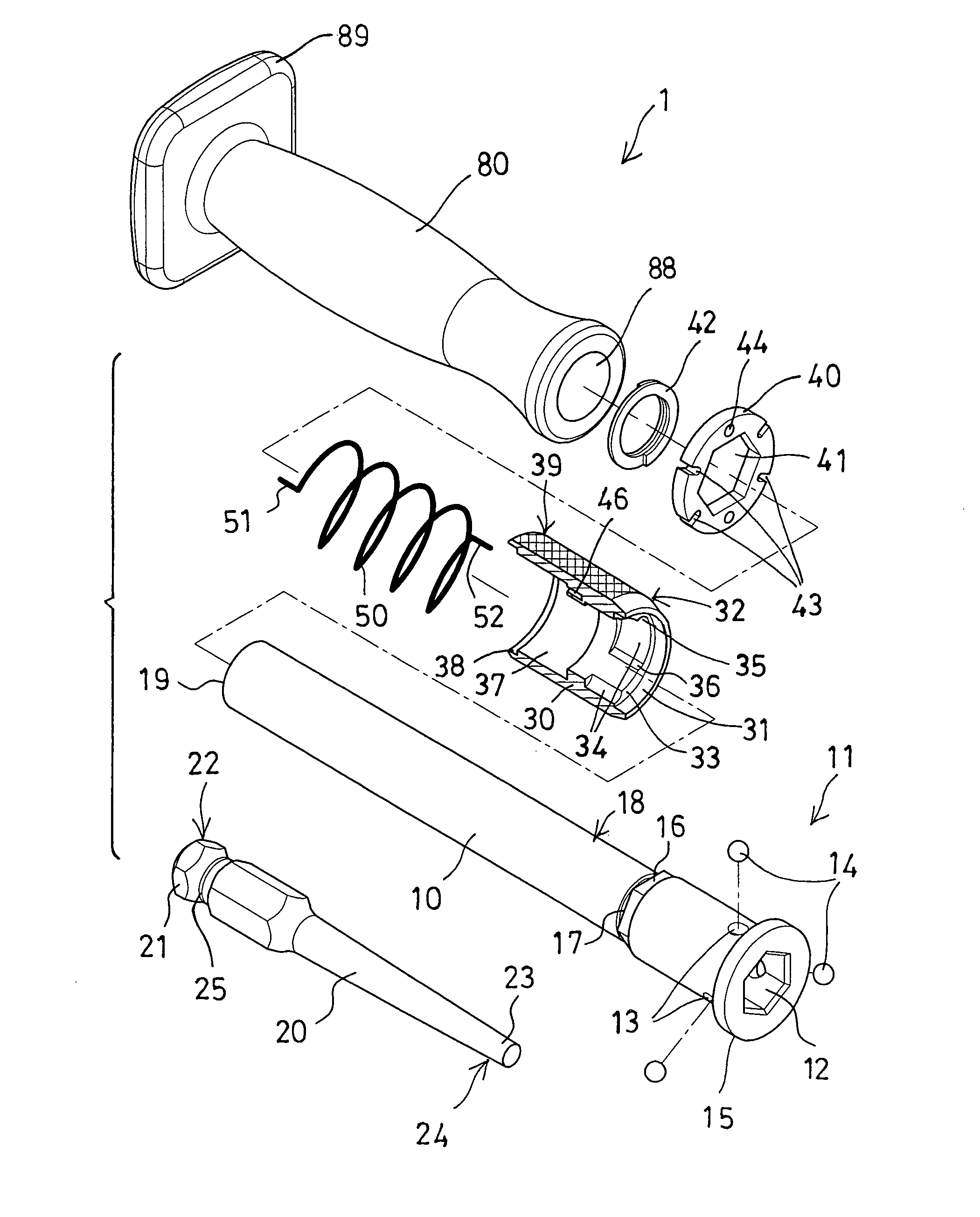
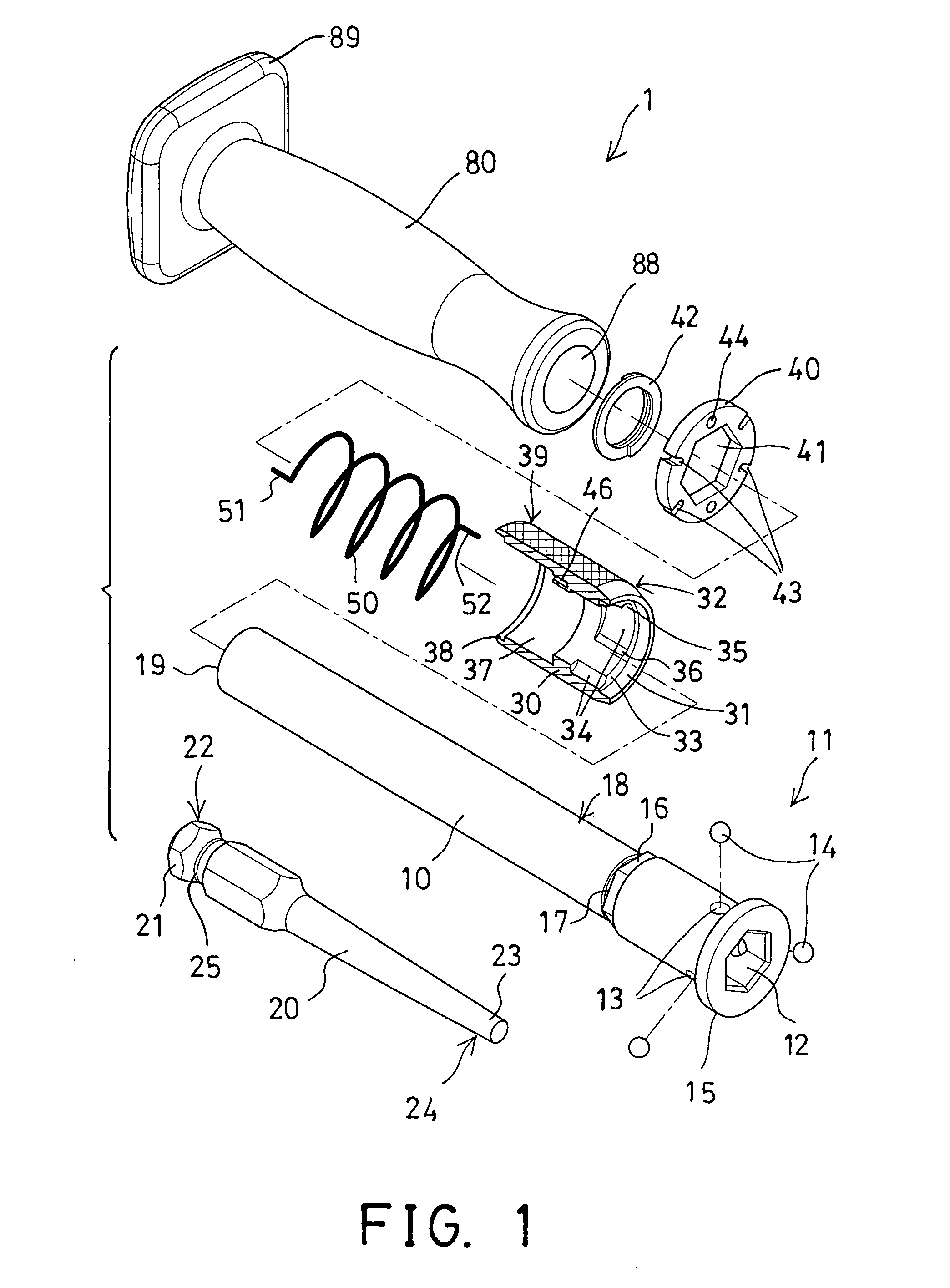
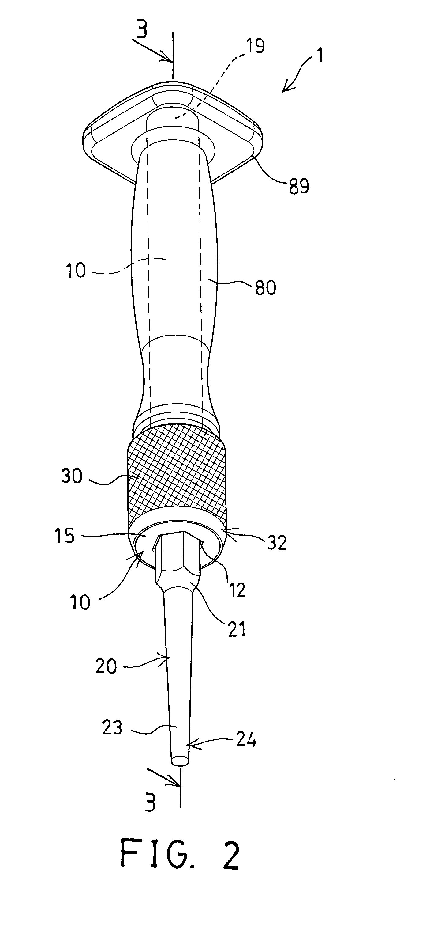
[0027]Referring to the drawings, and initially to FIGS. 1-3, a tool 1 in accordance with the present invention comprises a shaft or shank 10 including a first end or one end 11 having an engaging hole 12 formed therein and preferably having a noncircular cross section, such as a square or hexagonal cross section, for replaceably or changeably attaching or receiving a tool bit or tool member 20, such as a tool member 20 for a chisel or punch or chopper or percussion tool or driving tool or trimmer or impact tool or striking tool or other tools 1. For example, the tool member 20 includes an enlarged head 21 formed or provided on one end or first end 22 thereof and having a noncircular cross section for engaging into the corresponding noncircular engaging hole 12 of the shank 10 and for allowing the tool member 20 to be rotated or driven or operated by the shank 10.

[0028]The tool member 20 further includes a tool bit 23 formed or provided on the other end or second end 24 thereof for a...


PUM


Abstract

A tool includes a shank having an engaging hole for receiving one end of a tool member and having a number of orifices for receiving detents, a control ferrule rotatably engaged onto the shank and having a number of notches each of which includes a deeper portion for selectively receiving the detents and for disengaging the detents from the tool member and a shallower portion for selectively forcing and actuating the detents to engage with the tool member and to detachably couple the tool member to the shank, and a spring member may actuate the shallower portions of the notches of the control ferrule to engage with the detents and then to detachably couple the tool member to the shank.

Description

BACKGROUND OF THE INVENTION[0001]1. Field of the Invention[0002]The present invention relates to a tool or chisel or punch or chopper, and more particularly to a chisel tool including a clamping chuck for replaceably or changeably attaching the tool bits or tool members and for quickly and solidly securing the tool bits or tool members to the chisel.[0003]2. Description of the Prior Art[0004]Typical tool devices or tool apparatuses, such as chisels or punches or choppers or percussion tools or driving tools or trimmers or impact tools or striking tools comprise a tip or tool bit or tool member formed or provided on one end thereof for acting onto the workpieces.[0005]For example, U.S. Pat. No. 7,718,878 to Rompel discloses one of the typical chisels also comprise a shaft or shank or handle having a tip formed or provided on one end thereof for acting onto the workpieces.[0006]However, the tip is solidly formed or provided or secured to the shank and may not be removed from the shank...

Claims


Application Information

Patent Timeline
Patent Type & Authority Patents(United States)
IPC IPC(8): B23B31/22
CPCB25D3/00B25D2250/111Y10T279/17803Y10T279/17717Y10S279/905
Inventor LIN, HUNG WEI
Owner LIN HUNG WEI
Why Eureka
Try Eureka