
Mobile device

a mobile device and battery technology, applied in the field of mobile devices, can solve the problems of complicated structure of the lid and body, the problem of waterproof rendering of the battery chamber, and the inability to meet the needs of mobile devices, and achieve the effect of increasing the size of the mobile devi

Inactive Publication Date: 2011-09-20
FUJITSU CONNECTED TECH LTD
View PDF5 Cites 38 Cited by
  • Summary
  • Abstract
  • Description
  • Claims
  • Application Information

AI Technical Summary

Benefits of technology

[0010]It is an object of the embodiment to provide a mobile device in which a battery chamber and its periphery is rendered sufficiently waterproof without increasing the size of the mobile device.

Problems solved by technology

Where the waterproof function is incorporated in the mobile device that has a housing in which a large opening is defined for the battery chamber for loading the battery therein, rendering the battery chamber waterproof poses a problem.
However, depressing the lid from directly above the battery chamber, while keeping the lid and body joined, requires a complicated structure.
This frustrates the demand for a more compact design.
However, in this case, a structure in which the rotation shaft is pivotally supported by the body so as to be freely rotated may increase the size of the mobile device.
Therefore, how to always keep the sideways force, that is, torsion of the packing or O-ring within permissible levels poses a problem.

Method used


Image

  • Mobile device
  • Mobile device
  • Mobile device

Examples


Embodiment Construction

[0031]The mobile device disclosed in the preferred embodiment will be described below in detail with reference to figures.

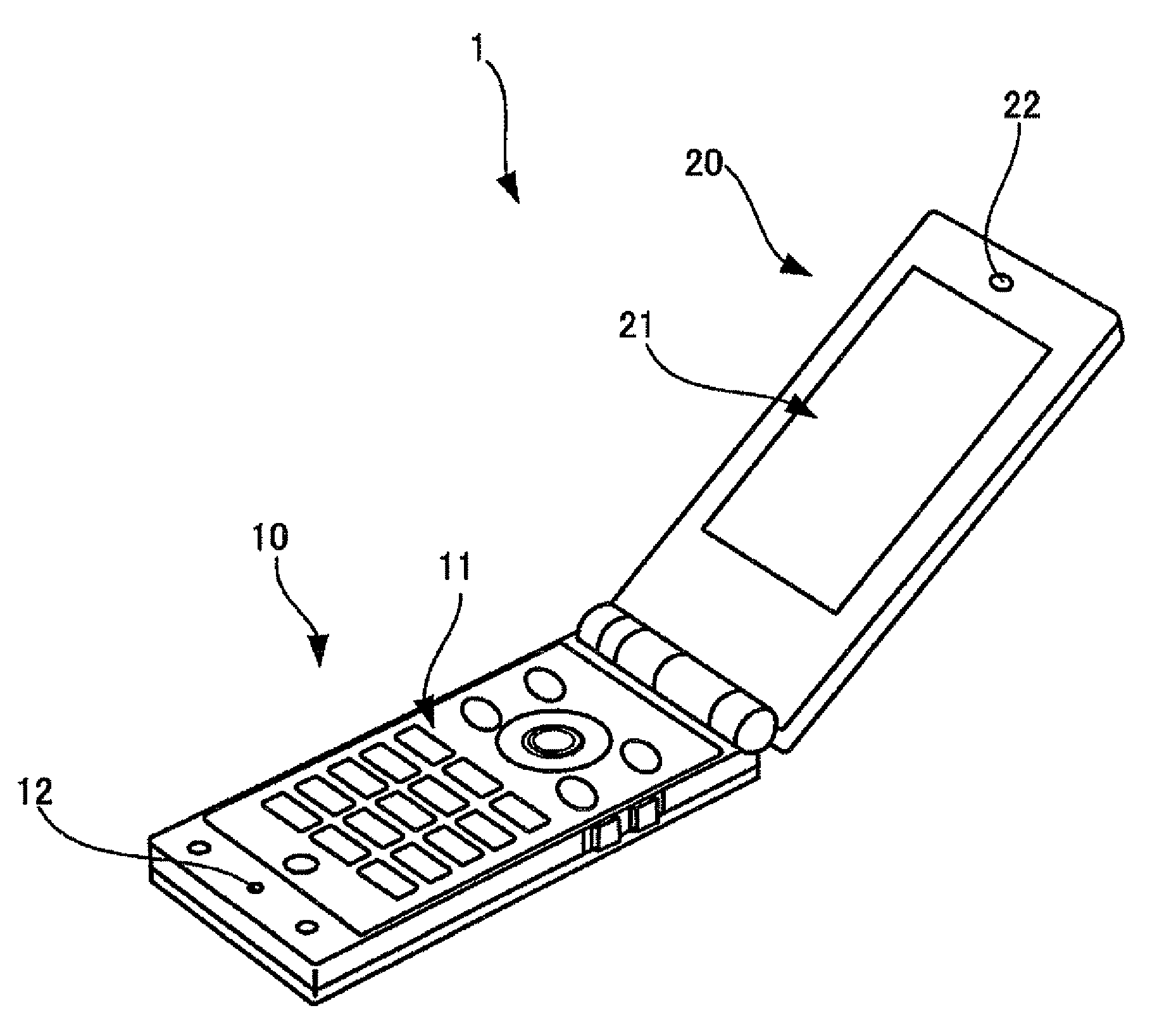
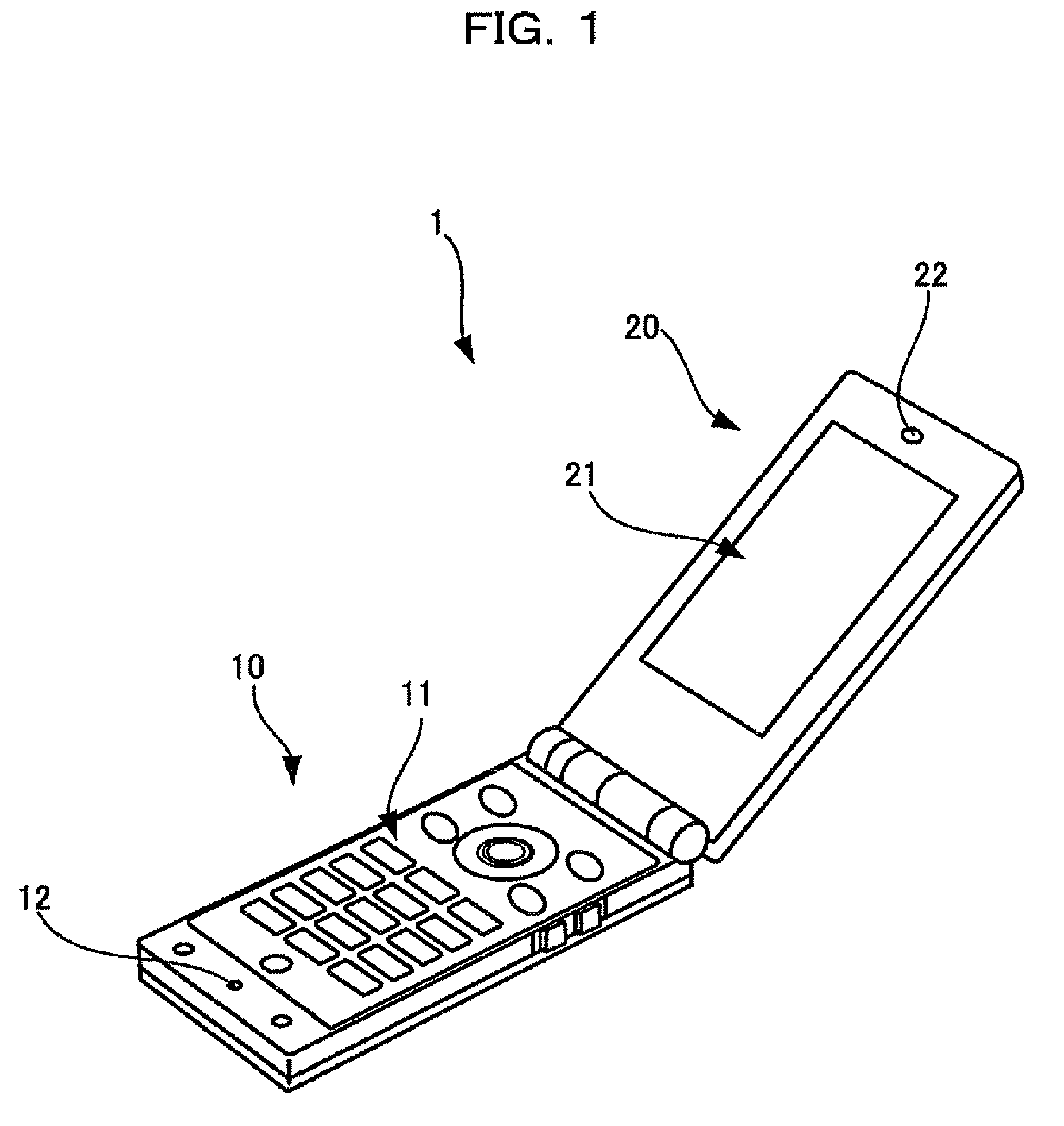
[0032]FIG. 1 is a perspective view of the appearance of a mobile phone that is an embodiment of the mobile device disclosed in the preferred embodiment.

[0033]The mobile phone 1 includes a body unit 10 and a display unit 20. The display unit 20 is pivotally supported by the body unit 10 so that it may be opened or closed.

[0034]Disposed on the body unit 10 are a number of keys 11 for inputting telephone numbers or various other information by a user. Disposed at the lower end of the body unit 10 is a mouthpiece 12 connected to a microphone disposed inside.

[0035]The display unit 20 has in its central area a display screen 21 for displaying images. Above the display screen 21 is an earpiece 22 for outputting sound from a sound producer disposed inside.

[0036]Loaded in the mobile phone 1 is a battery pack, and the mobile phone 1 runs on power supplied from the battery ...


PUM

PropertyMeasurementUnit
slide distanceaaaaaaaaaa
poweraaaaaaaaaa
shapeaaaaaaaaaa

Abstract

A mobile device having a housing and operating on power supplied from the battery loaded in the battery chamber including: a pair of walls of the housing having hook receiving portions formed a groove; a battery lid covering the battery chamber so as to be freely detached; a pair of positioning hooks serving to position the battery lid by entering the grooves of the corresponding hook receiving portions; overhanging edges serving to regulate position of the cover lid; and a waterproof gasket fixed to the battery chamber side of the cover lid so as to be in contact with all sides of the battery chamber.

Description

CROSS-REFERENCE TO RELATED APPLICATIONS[0001]This application is based upon and claims the benefit of priority of the prior Japanese Patent Application No. 2007-281995, filed on Oct. 30, 2007, the entire contents of which are incorporated herein by reference.BACKGROUND[0002]1. Field[0003]An aspect of the invention relates to a mobile device that has, for example, a housing defining a battery chamber in which a battery is loaded, and a battery lid covering the battery chamber so as to be freely detached, and that runs on power supplied from the battery loaded in the battery chamber.[0004]2. Description of the Related Art[0005]Recently, the use of mobile devices such as mobile phones and handheld video game machines has greatly increased. Most of such mobile devices have batteries loaded therein and run on power supplied from the batteries.[0006]While these mobile devices such as mobile phones incorporate more sophisticated functions, the device size and weight are further reduced. No...

Claims


Application Information

Patent Timeline
Patent Type & Authority Patents(United States)
IPC IPC(8): H04M1/00
CPCH04M1/0262H04M1/18H04M1/0214
Inventor ARAKI, TATSUHITOMATSUDA, HIROAKIMATSUMOTO, YOSHIYASOTODATE, MANABUMURATA, WATARUSHOJI, KENHATTORI, RYO
Owner FUJITSU CONNECTED TECH LTD
Learn More