AI technical title is built by Patsnap AI team. It summarizes the technical point description of the patent document.
a technology of shut off valve and ink manifold, which is applied in the direction of printing, other printing apparatus, etc., can solve the problems of reducing the exertion required to establish the seal fluid coupling, and affecting the efficiency of the ink supply
Active Publication Date: 2011-09-27
MEMJET TECH LTD +1
View PDF12 Cites 5 Cited by
Summary
Abstract
Description
Claims
Application Information
AI Technical Summary
This helps you quickly interpret patents by identifying the three key elements:
Problems solved by technology
Method used
Benefits of technology
Benefits of technology
[0016]Preferably, the fluid flow paths are partially defined by a polymer channel molding having an arrangement of channels and a flexible polymer film sealed over the channels to seal the fluid flow paths from each other, the shut off valves being sealed within the polymer channel molding by the flexible polymer film and the actuator configured to act on an external surface of the flexible polymer film at areas adjacent the shut off valves. Heat sealing a polymer film to a plastic molding is an exceptionally cheap and effective means of providing the sealed flow paths within a fluid manifold. The flexible film allows the actuator to push on the individual shut off valves while remaining sealed from the ink. Accordingly, the actuator can be metal for strength, without the potential problems associated with direct ink contact discussed above. Preferably, the flexible sealing film is polypropylene film foil.
Problems solved by technology
The high print speeds require a large ink supply flow rate.
Not only are the flow rates higher but distributing the ink along the entire length of a pagewidth printhead is more complex than feeding ink to a relatively small reciprocating printhead.
This recognizes that individual ink ejection nozzles may fail over time and eventually there are enough dead nozzles to cause artifacts in the printed image.
The supply flowrate to the pagewidth printhead is too high for needle valves because of the narrow internal diameter.
This requires the coupling conduits to be relatively large and therefore residual ink leaks freely out of the conduits once decoupled from the supply.
In pagewidth printhead cartridges, the leakage problem is exacerbated by the length of the ink flow paths.
Unfortunately, these are unsuitable for the specific requirements of a consumable component such as an ink jet cartridge.
Reaction between the ink and metal can create artifacts in the print.
Secondly, coupling the cartridge to the printer involves relatively high tolerances so that installation is fast and simple.
Method used
Image
Click on the blue label to locate the original text in one second.
Reading with bidirectional positioning of images and text.
Examples
Embodiment Construction
[0053]The invention will be described with specific reference to a fluid coupling between an inkjet print engine and its corresponding printhead cartridge. However, the ordinary worker will appreciate that the invention is equally applicable to other arrangements requiring a detachable fluid connection.
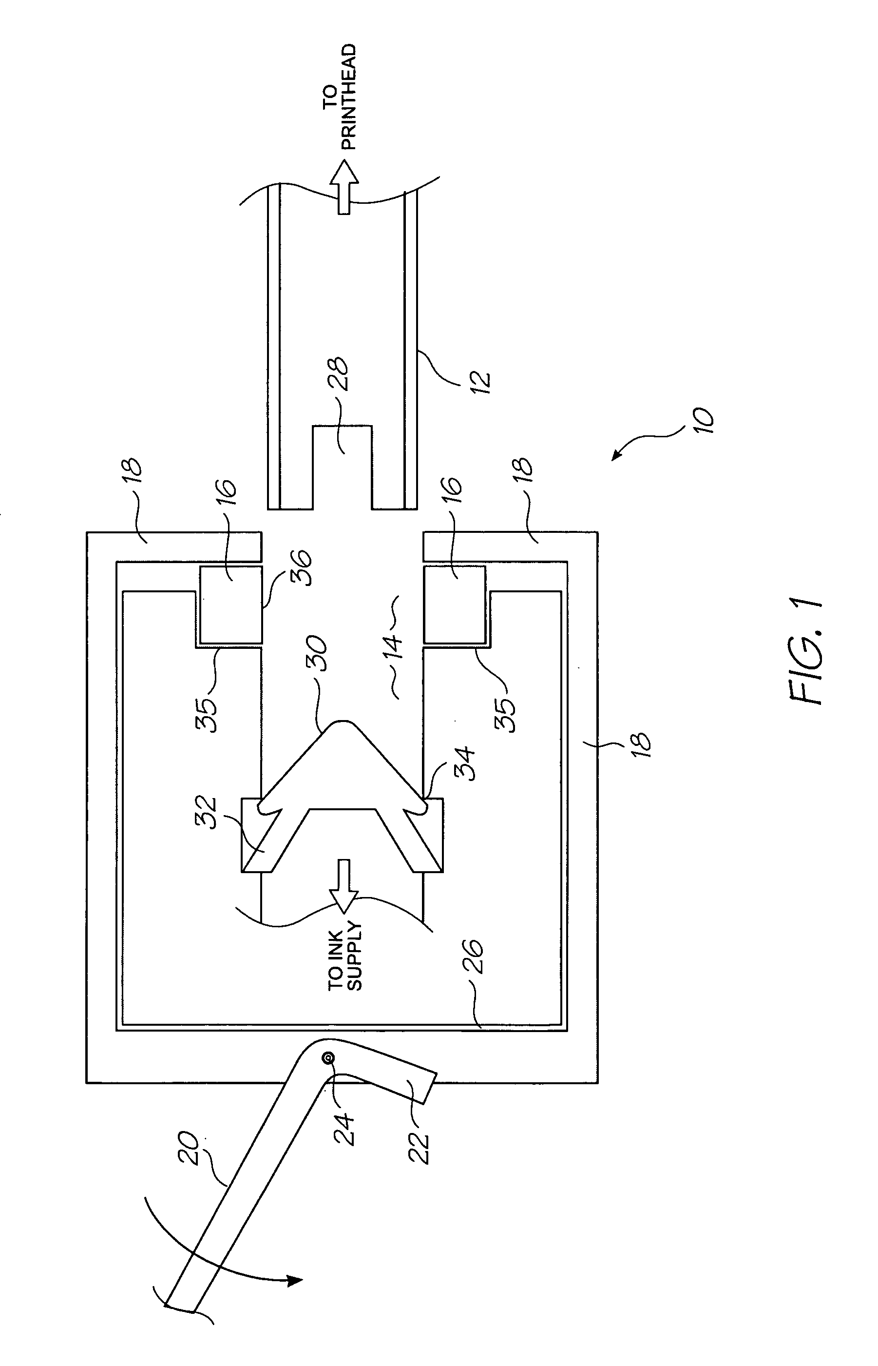
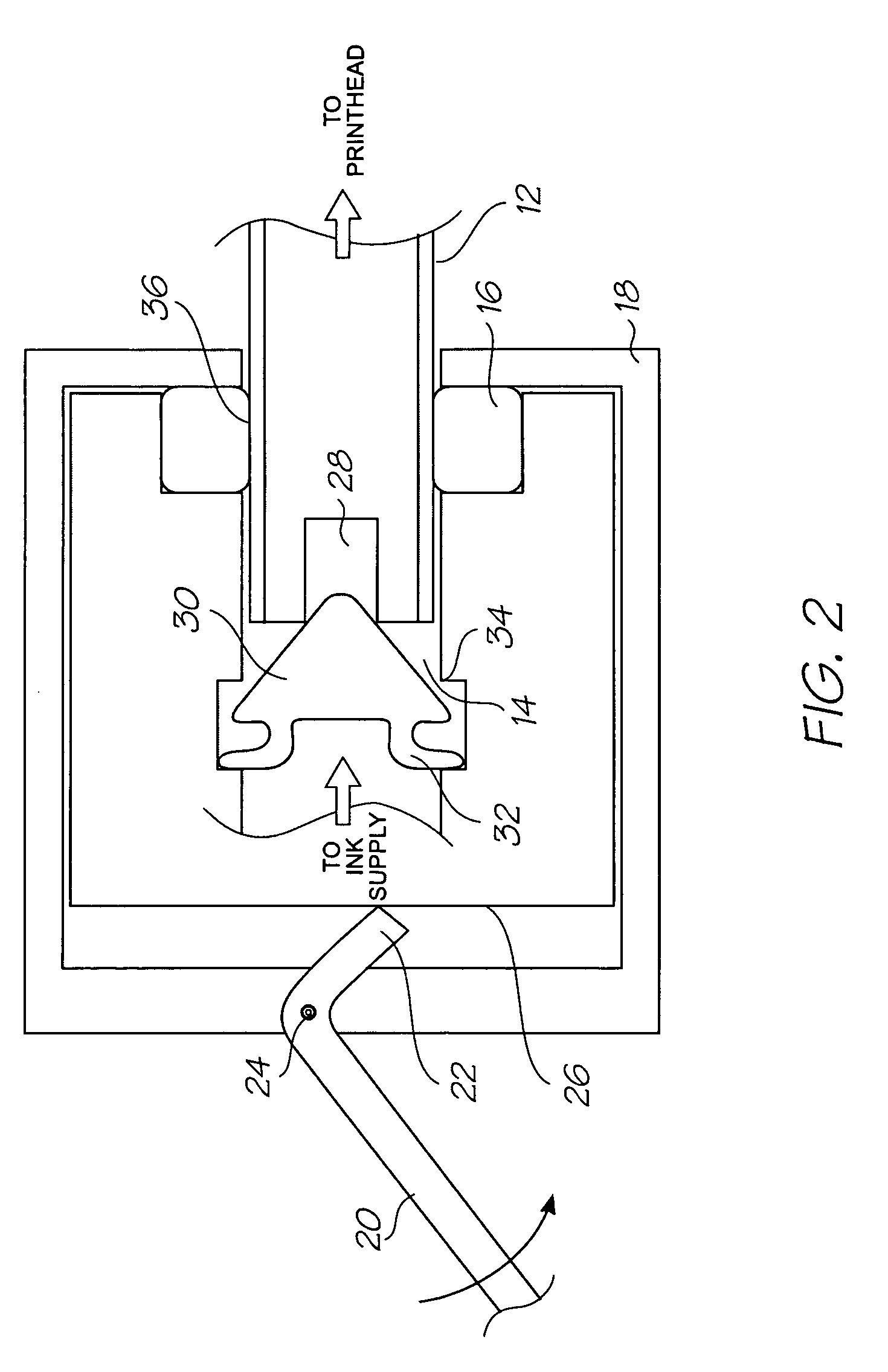
[0054]In FIG. 1, the fluid coupling 10 is shown with the first conduit 12 disengaged from the second conduit 14. The first conduit 12 leads to the pagewidth printhead of the removable printhead cartridge (described below). The second conduit 14 is connected to the ink supply (not shown) and sized such that it can telescopically engage the first conduit 12 with a sliding fit. The ink is retained by the shut off valve 30 biased against valve seat 34 by the resilient struts 32. The second conduit 14 defines a seal seat 35 for the annular seal 16. The annular seal 16 is retained in the seal seat 35 by the compression member 18. In the disengaged position shown in FIG. 1, the annular seal ...
PUM
Abstract
An ink manifold defining multiple fluid flow paths has openings arranged for detachable connection with conduits in an interface. Shut off valves at each of the openings respectively, are biased open. An actuator biased to a closed position by a resilient element, where it holds all the shut off valves closed. The actuator engages the interface such that moving the interface into connection with the openings simultaneously moves the actuator to an open position where the shut off valves are able to open. The resilient element generates a bias greater than a combined bias exerted by the shut off valves on the actuator.
Description
FIELD OF THE INVENTION[0001]The present invention relates to fluidic couplings and in particular, ink couplings within inkjet printers.CROSS REFERENCES[0002]The following patents or patent applications filed by the applicant or assignee of the present invention are hereby incorporated by cross-reference.[0003]11 / 246,68711 / 688,87312,014,77112,014,77211 / 482,98211 / 482,98311 / 482,98411 / 495,81811 / 495,81911 / 677,04911 / 677,05011 / 677,05111,872,71911,872,71812,046,44961,033,35712,062,51412,062,51712,062,51812,062,52012,062,52112,062,52212,062,52312,062,52412,062,52512,062,52612,062,52712,062,52812,062,52912,062,53012,062,53112,192,11612,192,11712,192,11812,192,11912,192,12012,192,121BACKGROUND OF THE INVENTION[0004]The Applicant has developed a wide range of printers that employ pagewidth printheads instead of traditional scanning printheads. Pagewidth designs increase print speeds as the printhead does not traverse back and forth across the page to deposit a line of an image. The pagewidth pr...
Claims
Application Information
Patent Timeline
Application Date:The date an application was filed.
Publication Date:The date a patent or application was officially published.
First Publication Date:The earliest publication date of a patent with the same application number.
Issue Date:Publication date of the patent grant document.
PCT Entry Date:The Entry date of PCT National Phase.
Estimated Expiry Date:The statutory expiry date of a patent right according to the Patent Law, and it is the longest term of protection that the patent right can achieve without the termination of the patent right due to other reasons(Term extension factor has been taken into account ).
Invalid Date:Actual expiry date is based on effective date or publication date of legal transaction data of invalid patent.
Patent Type & AuthorityPatents(United States)
IPC IPC(8): B41J2/175B41J2/18
CPCB41J2/1721B41J2/175B41J2/1752B41J29/02
InventorBERRY, NORMAN MICHAELNAKAZAWA, AKIRASILVERBROOK, KIA

