
Header compression in a wireless communication network

a wireless communication network and header compression technology, applied in multiplex communication, data switching networks, instruments, etc., can solve the problems of decompressors not being able to decompress newly received packets, decompressors losing context, current header compression schemes have some drawbacks, etc., to achieve the effect of improving header compression/decompression

Inactive Publication Date: 2011-09-27
ALCATEL LUCENT SAS
View PDF29 Cites 55 Cited by
  • Summary
  • Abstract
  • Description
  • Claims
  • Application Information

AI Technical Summary

Benefits of technology

[0010]The present invention relates to improving header compression / decompression over the radio link. In particular, the present invention provides a local repair mechanism at the decompressor that assists the decompressor in recovering from a decompression failure event (e.g., packet loss / errors or out-of-sequence receipt of packets) without having to resynchronize the compressor and decompressor.

Problems solved by technology

However, current header compression schemes do have some drawbacks.
When there are large consecutive packet losses in the link layer and / or a large degree of packets out of order, the decompressor is not able to decompress newly received packets.
When decompression failure happens, the decompressor will loose its context.
As a result, during resynchronization between the compressor and decompressor, additional packet losses will occur, degrading the performance and quality of the call.

Method used


Image

  • Header compression in a wireless communication network
  • Header compression in a wireless communication network
  • Header compression in a wireless communication network

Examples


Embodiment Construction

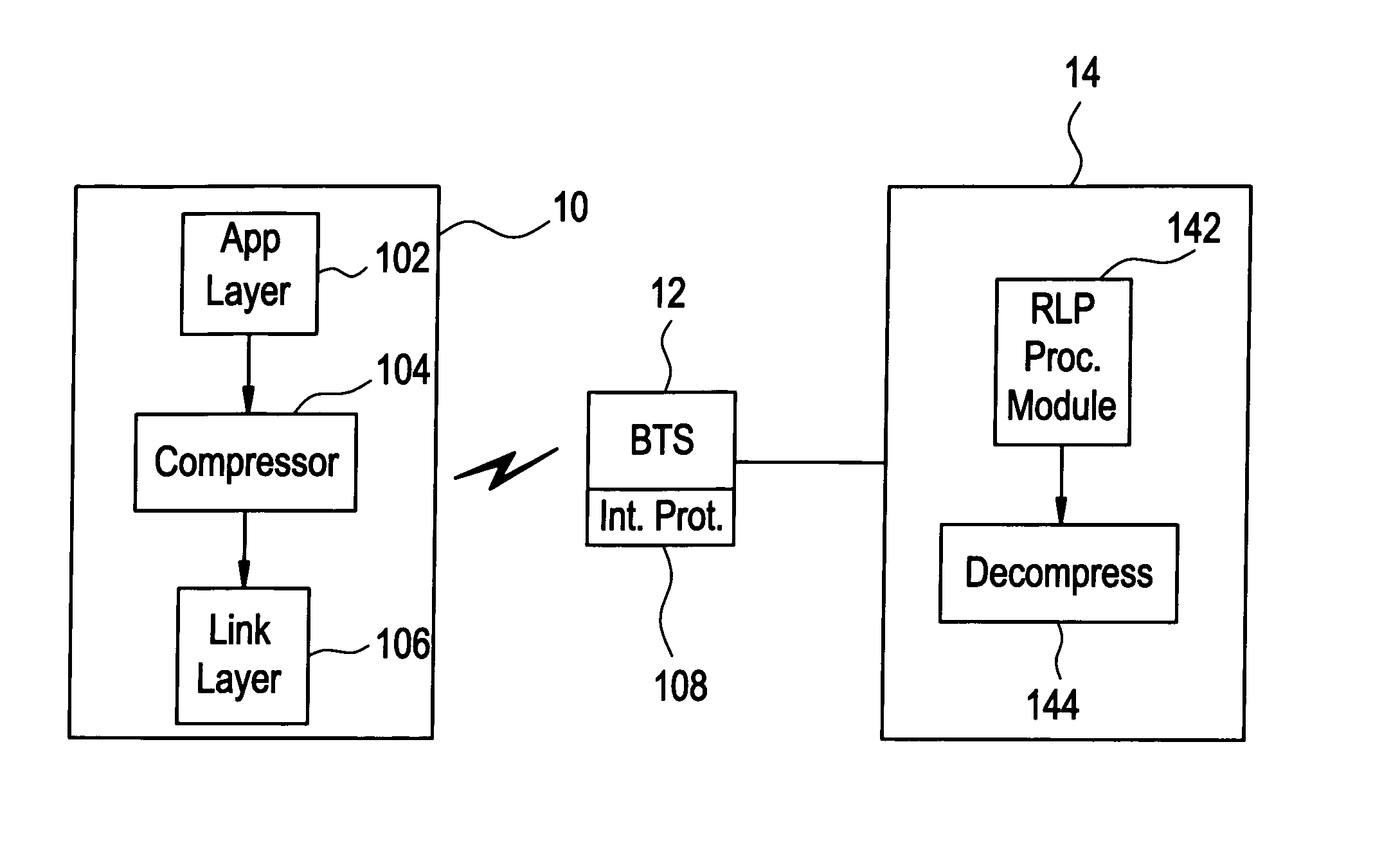
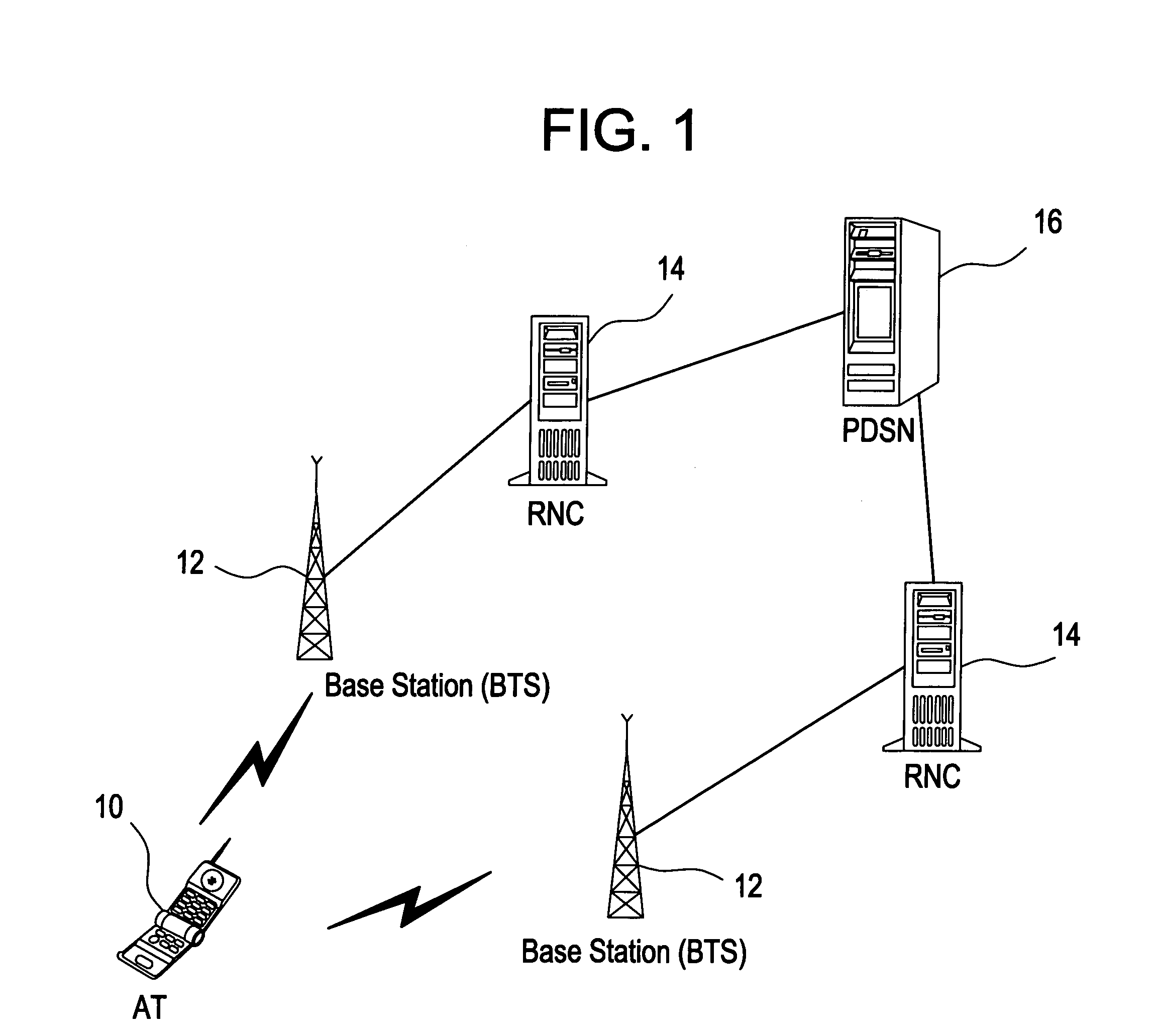
[0021]Referring to FIG. 1 discussed above, data packet transmissions over the link layer of the wireless network contain information to ensure packet delivery and processing at the RAN. For example, the radio link protocol (RLP) layer at a transmitter encapsulates the RoHC packet and provides a sequence number (SN) in an RLP header for packet delivery. The sequence number is incremented for each RLP packet transmission, and therefore, provides a mechanism for properly ordering packets received out-of-order at the receiver. This mechanism may also be used to recognize missing data packets.

[0022]Furthermore, the interface over the backhaul between the BTS 12 and RNC 14 adds another protocol (hereinafter “BTS / RNC interface protocol”) for encapsulating the RLP packets. More specifically, the BTS / RNC interface protocol maintains timing information (e.g., a time stamp) on when RLP packets are sent between the BTS and the RNC. On the reverse link, this timing information represents the tra...


PUM


Abstract

In one embodiment, a relationship is determined between radio link protocol (RLP) sequence numbers in received RLP packets and real-time protocol (RTP) sequence numbers in RTP packets decompressed from the received RLP packets. An RTP sequence number associated with a compressed RTP packet is determined based on the determined relationship and at least one of the RLP sequence numbers of the received RLP packet or packets forming the compressed RTP packet. An RTP time stamp may be determined in a similar manner.

Description

BACKGROUND OF THE INVENTION[0001]The Internet Protocol (IP) has become the dominant transport protocol in both wireline and wireless networks, which has led to the convergence of telecommunication and data networks. In many services and applications (e.g., Voice over IP (VoIP), interactive games, instant messaging, etc.), the payload of an IP packet is almost of the same size or even smaller than the header. In addition to the IP network protocol, other protocols (e.g., real-time protocol (RTP), user datagram protocol (UDP), etc.) are added to the original information bits for effective transport in a packet data network.[0002]Fortunately, it is not necessary to send the enormous RTP / UDP / IP header for each packet all the time. Instead a header compression algorithm such as the robust header compression (RoHC) may be used. The principle behind header compression is that most of the fields in the RTP / UDP / IP header are static; hence they can be sent once uncompressed during a first com...

Claims


Application Information

Patent Timeline
Patent Type & Authority Patents(United States)
IPC IPC(8): H04J3/24H04J3/00H04J3/16H04L12/28G06F15/16H04B1/00
CPCH04L1/0079H04L1/0091H04L47/34H04W28/06H04L69/04H04L69/40H04L69/10H04L65/608H04L65/65
Inventor YANG, TOMAS S.ZHANG, QINQING
Owner ALCATEL LUCENT SAS
Learn More