Backrest assembly

a backrest and assembly technology, applied in the field of backrest assembly, can solve the problems of affecting the appearance, unable to maintain the tightness of the net, and b>3/b>′ being liable to loosen, so as to achieve reliable and durable

Inactive Publication Date: 2011-10-04
SU TUNG HUA
View PDF13 Cites 130 Cited by
  • Summary
  • Abstract
  • Description
  • Claims
  • Application Information

AI Technical Summary

Benefits of technology

[0006]An objective of the present invention is to provide a backrest assembly that is reliable and durable.
[0007]Another objective of the present invention is to provide a backrest assembly that is more aesthetic in appearance.
[0008]A further objective of the present invention is to provide a backrest assembly that is easy to recycle.

Problems solved by technology

Some of the nails 3′ are liable to loose when the lying force is large or not applied to a center of the backrest.
Furthermore, the net 2′ can not be maintained in its tightened state.
Further, the fixing holes 11′ and the screws 5′ can be viewed from the rear side of the backrest, adversely affecting the appearance.
Further, recycling of the backrest is not easy due to difficulties in removing the nails 3′ before separating the net 2′ from the frame 1′.

Method used


Image

  • Backrest assembly
  • Backrest assembly
  • Backrest assembly

Examples


first embodiment

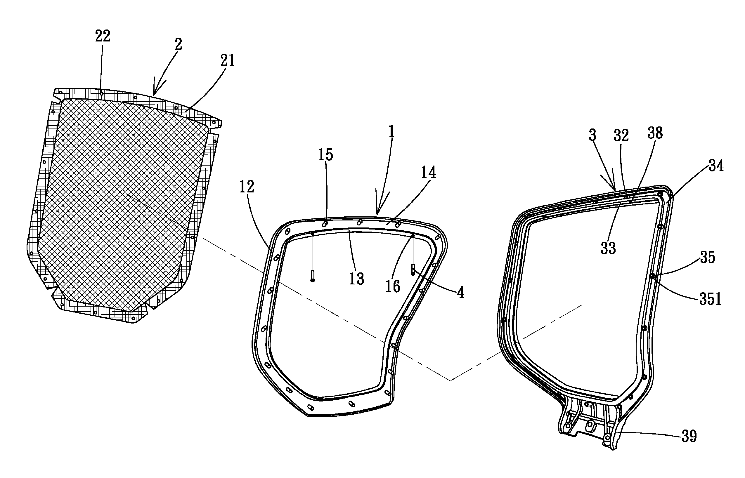
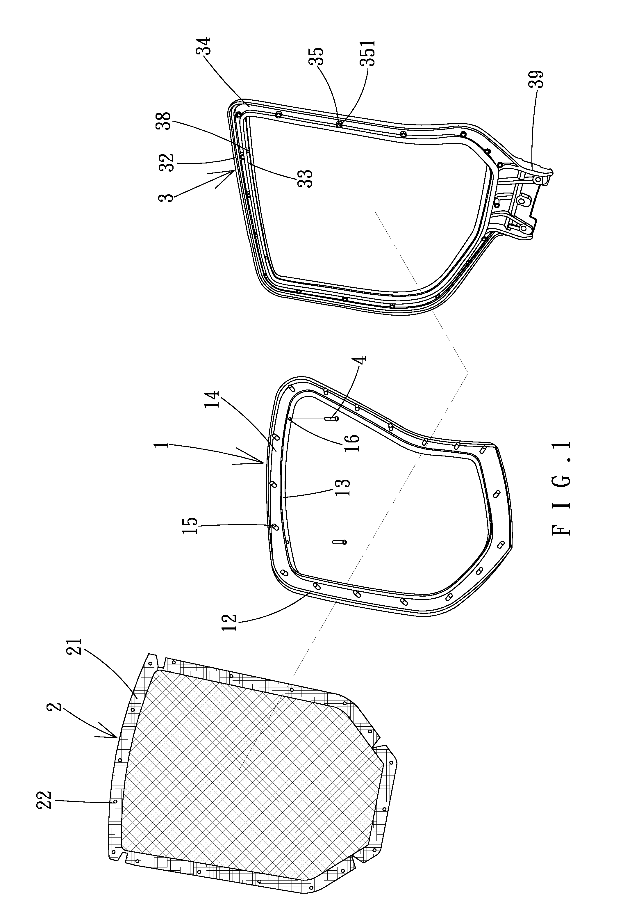
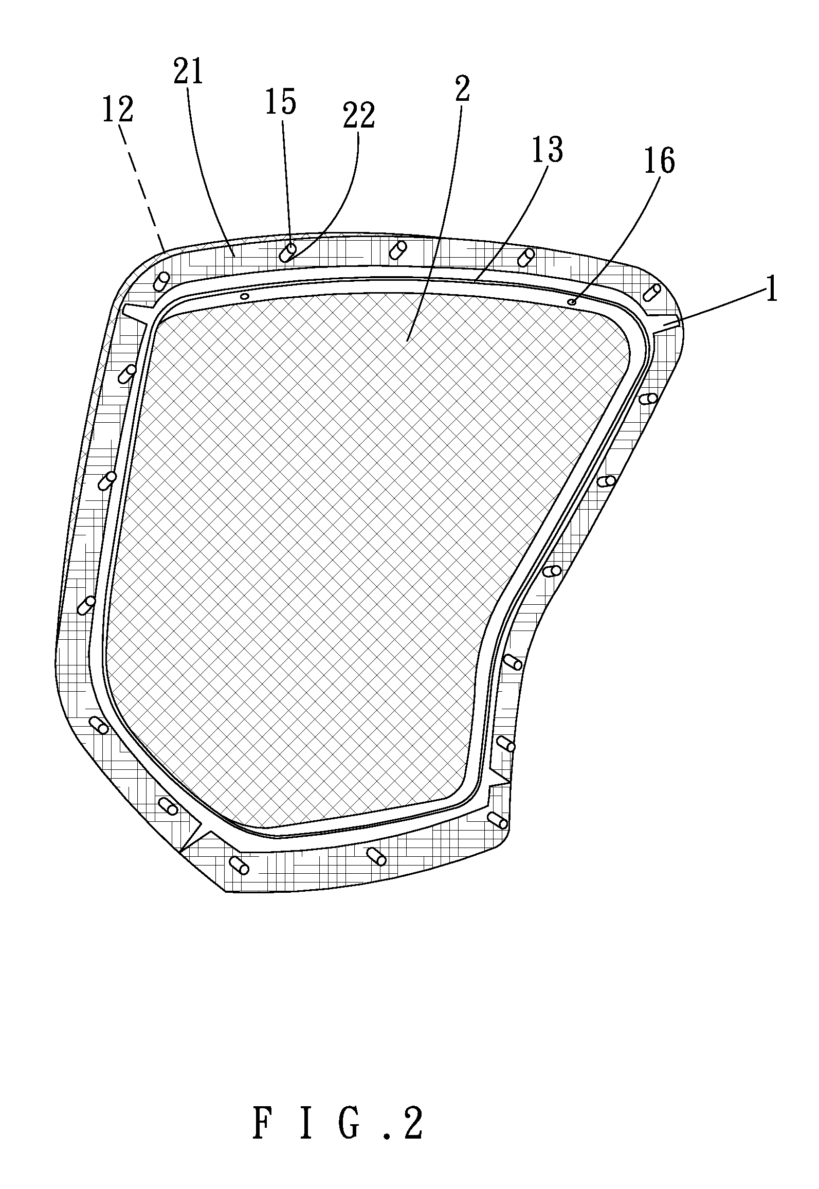
[0023]A backrest assembly of a first embodiment according to the preferred teachings of the present invention FIGS. 1-6 and generally includes a front frame 1, a net 2, a rear frame 3, and a plurality of fasteners 4. The front frame 1 is annular and made of rigid material and includes front and rear surfaces 11 and 18 spaced in a first direction. An outer annular flange 12 is formed along a peripheral edge of the rear surface 18. Furthermore, an inner annular flange 13 is formed on the rear surface 18 and surrounded by the outer annular flange 12, defining an annular groove 14 between the outer and inner annular flanges 12 and 13. A plurality of annularly spaced pegs 15 is formed on the rear surface 18 and in the annular groove 14. The inner annular flange 13 includes a plurality of engaging holes 16 extending in a second direction perpendicular to the first direction.

[0024]The net 2 is made of bendable material and includes a coupling member 21 fixed to a periphery of the net 2 suc...

second embodiment

[0028]FIG. 7 shows a backrest assembly of a second embodiment according to the preferred teachings of the present invention. In this embodiment, the spacing between the pegs (now designated by 51) of the front frame (now designated by 5) and the spacing between the stubs (now designated by 71) of the rear frame (now designated by 7) are larger. The pegs 51 of the front frame 5 are extended through the peg holes (now designated by 61) of the net (now designated by 6) to maintain the net 6 in the tightened state. Furthermore, a portion of the net 6 are fixed by nails 8 to the front frame 5. Thus, even the backrest assembly is subjected to the lying force from the user, the nails 8 will not become loose, providing stable, reliably assembly.

[0029]It can be appreciated that the net can be made of tear-resistant material, so that the net does not have to include the coupling member having the peg holes. Instead, the peg holes can be directly formed in the net.


PUM


Abstract

A backrest assembly includes an annular front frame having a front surface on which inner and outer annular flanges are formed, defining a first annular groove therebetween. A plurality of pegs is formed in the annular groove. A net is mounted in front of the front frame in a tightened state and includes a plurality of peg holes. A periphery of the net covers the outer annular flange of the front frame and is received in the first annular groove. Each peg of the front frame extends through one of the peg holes. Inner and annular wall are formed on a front face of an annular rear frame and define a second annular groove therebetween. A plurality of stubs is formed in the second annular groove. Each stub includes a receptacle receiving one of the pegs. Fasteners are extended through engaging holes in the front and rear frames.

Description

BACKGROUND OF THE INVENTION[0001]1. Field of the Invention[0002]The present invention relates to a backrest assembly and, more particularly, to a back assembly that is reliable, durable, and easy to assemble.[0003]2. Description of the Related Art[0004]A backrest of a chair provides a support for a back of a user sitting in the chair. For venting purposes, the backrest is provided with a net. FIGS. 8 and 9 show a conventional backrest with a net. Specifically, the backrest includes an annular frame 1′ made of rigid material and having a plurality of fixing holes 11′. A flexible net 2′ is fixed by nails 3′ to an engaging portion 12′ on a front side of the frame 1′ to tighten the net 2′. A cover 4′ having a shape corresponding to the frame 1′ is mounted to the front side of the frame 1′. The cover 4′ includes a plurality of coupling holes 41′ aligned with the fixing holes 11′. Screws 5′ are extended through the fixing holes 11′ and the coupling holes 41′ to fix the cover 4′ and the fr...

Claims


Application Information

Patent Timeline
Patent Type & Authority Patents(United States)
IPC IPC(8): A47C7/02
CPCA47C7/40A47C31/023
Inventor SU, TUNG-HUA
Owner SU TUNG HUA
Why Eureka
Try Eureka