
System and method for pressure compensation in a pump

a pressure compensation and pump technology, applied in the field of fluid pumps, can solve the problems of sharp pressure spikes in liquid, high cost of photochemicals used in the semiconductor industry, and high cost of up to $1000 a liter, and achieve the effects of accurate dispense, elimination or reduction of disadvantages, and repeatability of dispenses

Active Publication Date: 2011-10-04
ENTEGRIS INC
View PDF205 Cites 37 Cited by
  • Summary
  • Abstract
  • Description
  • Claims
  • Application Information

AI Technical Summary

Benefits of technology

The solution effectively maintains a consistent baseline pressure, reducing the risk of fluid damage and ensuring accurate, repeatable dispensing, which enhances the efficiency and reliability of the dispensing process, particularly in semiconductor manufacturing.

Problems solved by technology

Many photochemicals used in the semiconductor industry today are very expensive, frequently costing as much as $1000 a liter.
Current multiple stage pumps can cause sharp pressure spikes in the liquid.
Such pressure spikes and subsequent drops in pressure may be damaging to the fluid (i.e., may change the physical characteristics of the fluid unfavorably).
Additionally, pressure spikes can lead to built up fluid pressure that may cause a dispense pump to dispense more fluid than intended or dispense the fluid in a manner that has unfavorable dynamics.
This pressure drift may be particularly detrimental when it occurs in a dispense chamber containing fluid awaiting dispense.

Method used


Image

  • System and method for pressure compensation in a pump
  • System and method for pressure compensation in a pump
  • System and method for pressure compensation in a pump

Examples


Embodiment Construction

[0025]Preferred embodiments of the present invention are illustrated in the FIGS., like numerals being used to refer to like and corresponding parts of the various drawings.

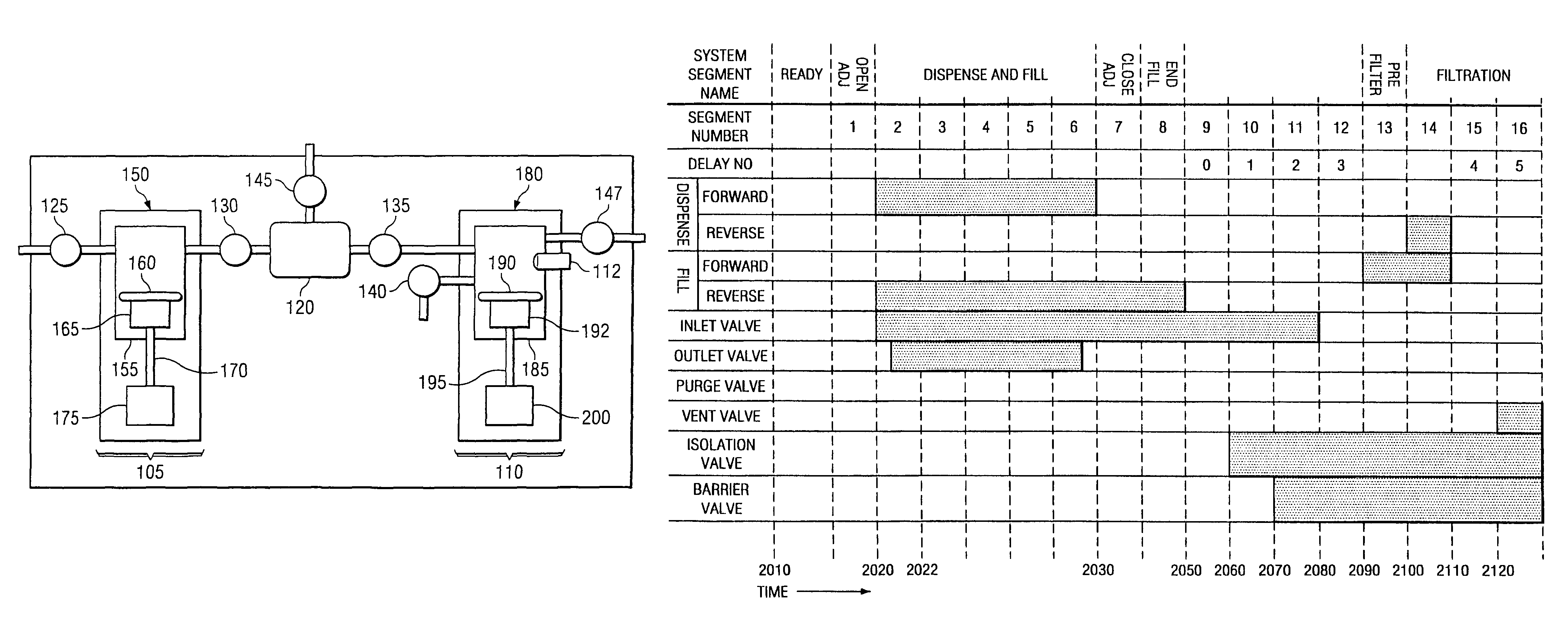
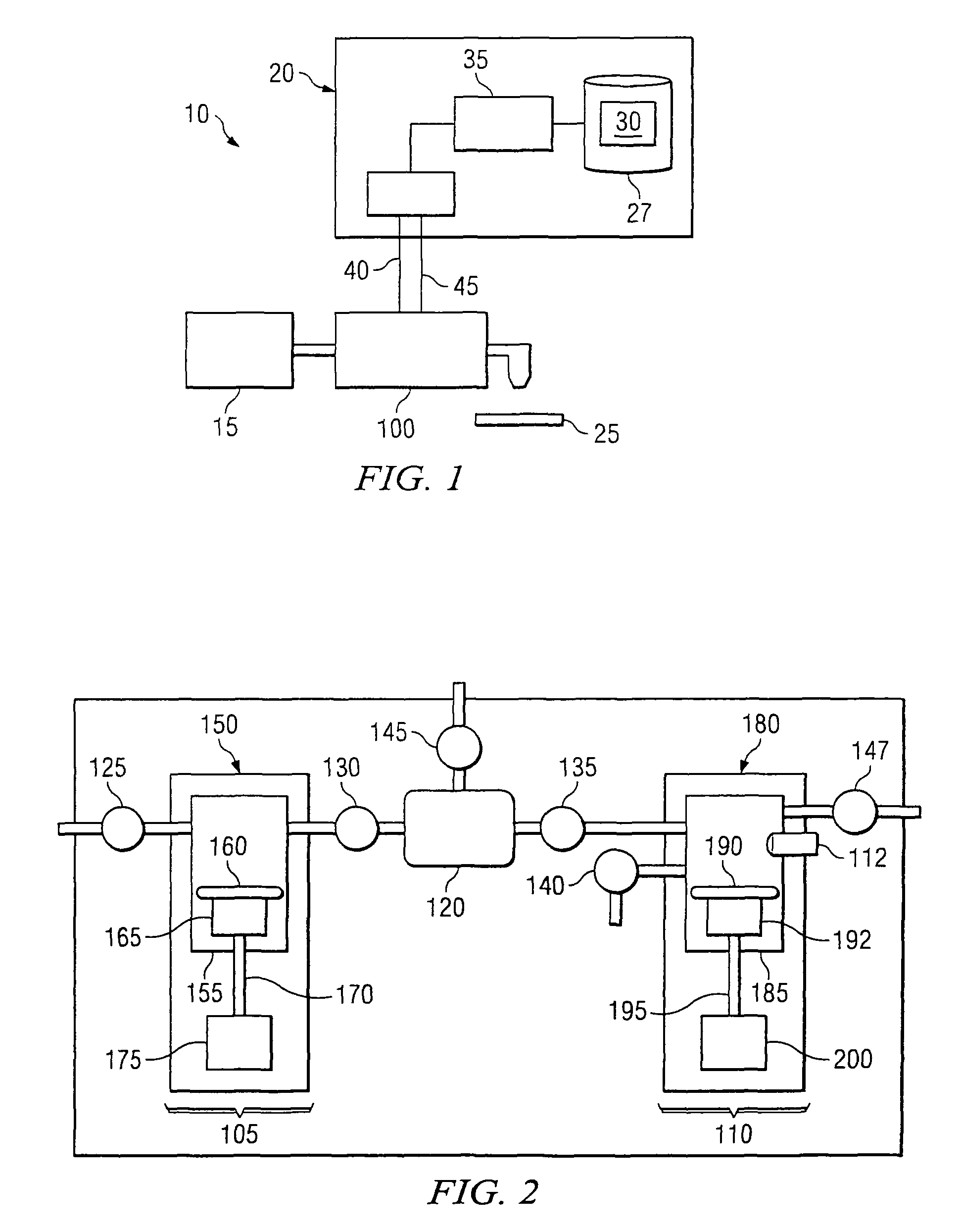
[0026]Embodiments of the present invention are related to a pumping system that accurately dispenses fluid using a pump, which may be a single stage pump or a multiple stage (“multi-stage”) pump. More particularly, embodiments of the present invention provide systems and methods for correcting for pressure drift which may occur in a ready segment of a dispense cycle of a multi-stage pump (e.g. because valves are closed creating a trapped space, for example within a dispense chamber). After entering a ready segment the pressure within a dispense chamber of the multi-stage pump may be monitored, and any pressure variation detected may be corrected for by moving a dispense stage diaphragm. Embodiments of such a pumping system are disclosed in U.S. Provisional Patent Application Ser. No. 60 / 742,435 by inventors James...


PUM


Abstract

Systems and methods for maintaining substantially a baseline pressure in a chamber of a pumping apparatus are disclosed. Embodiments of the present invention may serve to control a motor to compensate or account for a pressure drift which may occur in a chamber of the pumping apparatus. More specifically, a dispense motor may be controlled to substantially maintain a baseline pressure in the dispense chamber before a dispense based on a pressure sensed in the dispense chamber. In one embodiment, before a dispense is initiated a control loop may be utilized such that it is repeatedly determined if the pressure in the dispense chamber is above a desired pressure and, if so, the movement of the pumping means regulated to maintain substantially the desired pressure in the dispense chamber until a dispense of fluid is initiated.

Description

RELATED APPLICATIONS[0001]This application claims priority to U.S. Provisional Patent Application Ser. No. 60 / 741,682 by inventors George Gonnella and James Cedrone, entitled “System and Method For Pressure Compensation in a Pump” filed on Dec. 2, 2005, the entire contents of which are hereby expressly incorporated by reference for all purposes.TECHNICAL FIELD OF THE INVENTION[0002]This invention relates generally to fluid pumps. More particularly, embodiments of the present invention relate to multi-stage pumps. Even more particularly, embodiments of the present invention relate to compensating for pressure drift which may occur in a pump used in semiconductor manufacturing.BACKGROUND OF THE INVENTION[0003]There are many applications for which precise control over the amount and / or rate at which a fluid is dispensed by a pumping apparatus is necessary. In semiconductor processing, for example, it is important to control the amount and rate at which photochemicals, such as photoresi...

Claims


Application Information

Patent Timeline
Patent Type & Authority Patents(United States)
IPC IPC(8): F04B49/08B67D7/30
CPCF04B13/00F04B49/065F04B49/08F04B51/00F04B2205/03F04B49/00
Inventor CEDRONE, JAMESGONNELLA, GEORGE
Owner ENTEGRIS INC
Learn More