Electrically small antenna

a small, antenna technology, applied in the direction of antennas, antenna feed intermediates, antennas, etc., can solve the problems of difficult to detect, locate or map such underground facilities, radar does not penetrate the earth's surface, waves are reflected and attenuated, etc., to achieve efficient transmit/receive capability, light and efficient

Inactive Publication Date: 2011-10-04
THE BOEING CO
View PDF13 Cites 10 Cited by
  • Summary
  • Abstract
  • Description
  • Claims
  • Application Information

AI Technical Summary

Benefits of technology

[0011]Certain advantages of the embodiments of the invention described herein include an electrically small antenna (ESA) having the capability to resolve very small objects compared to the wavelength of an interrogation signal.
[0015]A yet further advantage of the present invention is to provide an ESA that is lighter and more efficient than a conventional dipole antenna.

Problems solved by technology

A key factor that makes it difficult to detect, locate or map such underground facilities is that conventional radar does not penetrate the Earth's surface.
When using conventional radar the electromagnetic waves are reflected and attenuated by the soil, due to the finite conductivity and dielectric loss of the soil.
However, since radar antennas are geometrically proportional to the wavelength, operating a radar system at frequencies as low as 10-150 kHz normally requires an enormous antenna.
Such an antenna cannot be carried efficiently by an airplane, and in any event may not radiate sufficient power to generate a ground-penetrating radar wave.
Further, the resolution of such a low frequency radar system would have limited diffraction properties.
Such a radar system would be diffraction limited and able to resolve only those objects or features of sizes comparable to the wavelength.
However, such GPRs at best penetrate the ground within about a meter of the Earth's surface.
However, many underground facilities are accessible by a rather long tunnel that leads from the excavation point to the final underground destination point, meaning that identifying the entrance point at the surface may provide an inaccurate indication of the location of the underground facility.
However, it is not always possible to place sensors, conceal them from discovery, and then periodically interrogate such sensors in the vicinity of such an underground facility.
Unless the ground sensors are placed in the exact location where detection of signals is likely, it would be easy to miss detection of the target.
Finally, the logistics and cost of placing a large number of sensors make placing acoustic sensors an impractical and unattractive solution.
However, these ESAs have not been configured to illuminate subterranean images.
Other limitations of the related art will become apparent to those of skill in the art upon reading of the specifications and study of the drawings.

Method used


Image

  • Electrically small antenna
  • Electrically small antenna
  • Electrically small antenna

Examples


Embodiment Construction

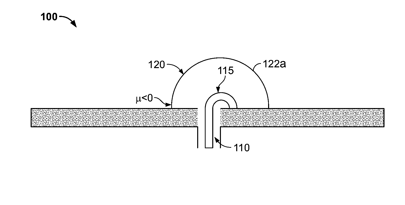
[0028]The ESA of the current invention is on the order of meters and has an efficient transmit / receive capability compared to a regular dipole. The ESA is constructed using metamaterial concepts. The metamaterial may be single negative (SNG) (i.e. the permittivity ε<0, or the permeability μ<0) or double negative (DNG) (i.e. both the permittivity ε<0 and the permeability μ<0). In an exemplary embodiment, an ESA is disclosed that is 1 / 10 of the length of the equivalent dipole length, and may be scaled down to 1 / 1000 or 1 / 10,000. Such an ESA may include phase sensitive current injection in the metamaterial resonant structures for loss-compensation. In other words, the unit cells of the ESA may be driven by a current source that is in phase with the exciting electromagnetic wave. The ESA may include a magnetic or electric dipole, and the metamaterial resonant structure may be a metamaterial shell or a metamaterial hemispherical structure. In one embodiment, the ESA includes a magnetic d...


PUM


Abstract

An electrically small antenna (ESA) for resolution of subwavelength features is disclosed. The ESA is on the order of meters and has an efficient transmit / receive capability. The ESA is 1 / 10 of the length of the equivalent dipole length, and may be scaled down to 1 / 10,000. The ESA includes a metamaterial shell. Such an antenna may include phase sensitive current injection in the metamaterial resonant structures for loss-compensation.

Description

BACKGROUND[0001]The application generally relates to electrically small antennas (ESAs). The application relates more specifically to ESAs including metamaterial resonant structure to reduce antenna size. The ESA may be mounted on an aircraft for the identification and mapping of subsurface facilities or features.[0002]One object of gathering intelligence data is the identification, mapping, and location of deeply buried underground facilities. The scientific community is interested in methods for locating and mapping underground facilities in non-accessible territory to determine, for example, whether underground nuclear facilities are situated in underground bunkers. A key factor that makes it difficult to detect, locate or map such underground facilities is that conventional radar does not penetrate the Earth's surface. When using conventional radar the electromagnetic waves are reflected and attenuated by the soil, due to the finite conductivity and dielectric loss of the soil.[...

Claims


Application Information

Patent Timeline
Patent Type & Authority Patents(United States)
IPC IPC(8): H01Q9/28
CPCH01Q1/28H01Q7/00H01Q9/16H01Q15/08H01Q15/0086
Inventor TANIELIAN, MINAS H.GREEGOR, ROBERT B.PARAZZOLI, CLAUDIO G.
Owner THE BOEING CO
Why Eureka
Try Eureka