Vehicle suspension comprising light weight leaf spring assembly

a technology of leaf springs and suspensions, which is applied in the direction of springs/dampers, mechanical equipment, transportation and packaging, etc., can solve the problems of relatively high cost of manufacturing tapered steel leaf springs, significantly more expensive than conventional flat springs, and relatively high cost of manufacturing tapered leaves. cost and weight reduction

Active Publication Date: 2014-12-04
VOLVO LASTVAGNAR AB
View PDF2 Cites 13 Cited by
  • Summary
  • Abstract
  • Description
  • Claims
  • Application Information

AI Technical Summary

Benefits of technology

[0028]A vehicle comprising a suspension provided with a leaf spring assembly according to the invention does not require to be secured by a safety system or safety device at each end. This is required for a standard leaf spring in case of spring failure. For a steered front axle, the safety eye provided at the front end to block to front axle dislocation can be eliminated. Similarly, the steel belt or blocker provided at the rear end can be dispensed w

Problems solved by technology

The cost of manufacturing a tapered steel leaf spring is relatively high because it requires the use of special tapered rolling machines.
As a result, although tapered single leaf springs are generally available today for use with larger vehicles, such as heavy trucks, they are significantly more expensive than conventional flat springs.
As previously mentioned, however, the cost of manufacturing such tapered leaves is relatively high.
One of the principal deficiencies of a built-up steel spring assembly is its weight.
In spite of these efforts, plastic and composite single leaf springs have not been used commercially for a variety of reasons.
It is generally accepted that springs made entirely of plastic would be impractical because of excessive bulk and insufficient resistance to wear and impact.
This spring has proven impractical due to high cost and its ex

Method used


Image

  • Vehicle suspension comprising light weight leaf spring assembly
  • Vehicle suspension comprising light weight leaf spring assembly
  • Vehicle suspension comprising light weight leaf spring assembly

Examples


Embodiment Construction

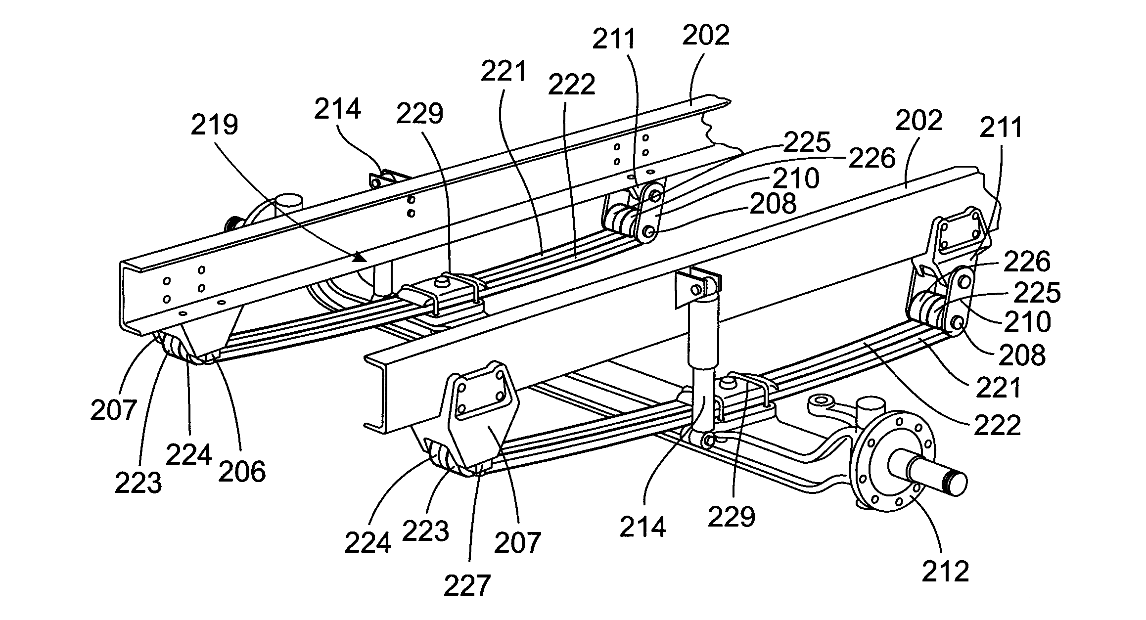
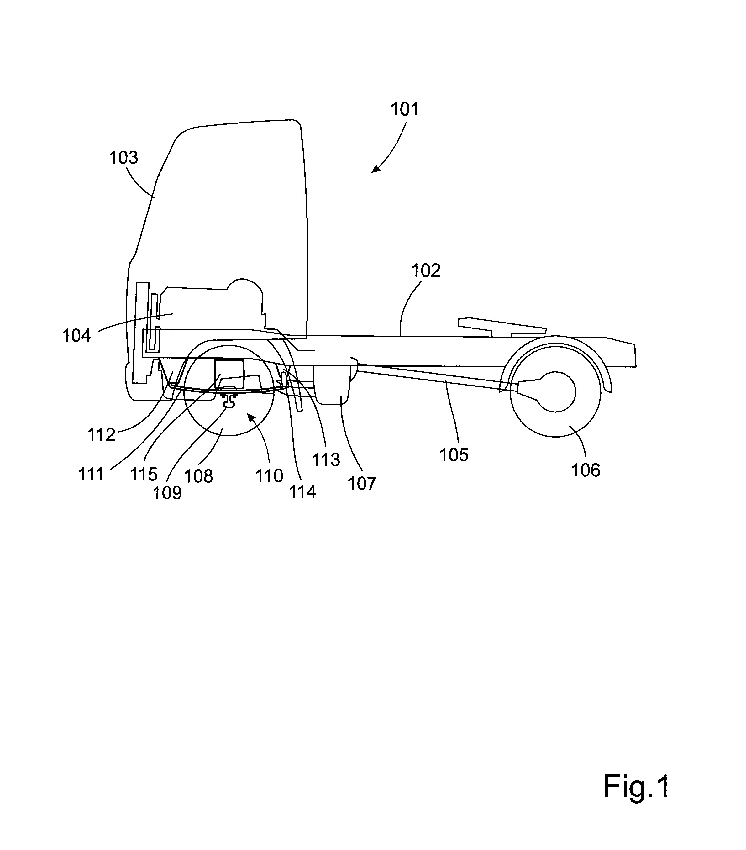
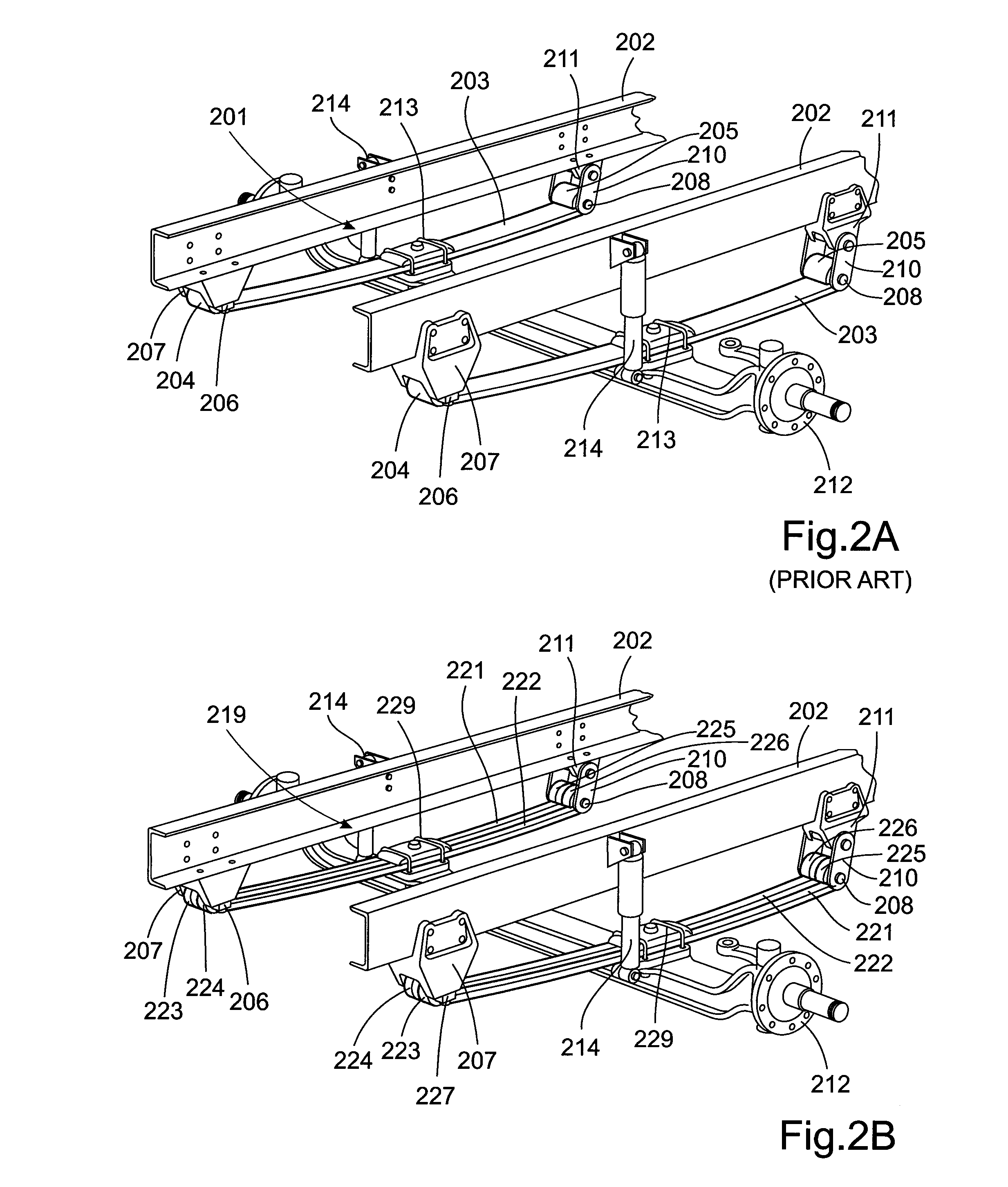
[0039]FIG. 1 shows a schematic commercial vehicle 101 in the form of a tractor unit. The commercial vehicle 101 comprises a chassis 102 and a driver's cab 103 mounted on the chassis. Underneath the driver's cab 103 is an internal combustion engine 104, which acts on a pair of drive wheels 106 of the commercial vehicle 101 by way of a drive train 105 comprising a clutch and a manual transmission or an automatic transmission. The internal combustion engine 104 comprises an exhaust gas system 107 with a first and a second muffler connected to a tailpipe (not shown) which expels the exhaust gases to the atmosphere. The cab 103 is also supported by a pair of steerable front wheels 108. The steerable wheels are mounted on a rigid axle 109 attached to a suspension arrangement 110. The suspension arrangement 110 comprises a leaf spring assembly 111 according to the invention supported by a front bracket 112 and a rear bracket 113 with a spring shackle 114. In the example shown in FIG. 1 the...


PUM


Abstract

A vehicle suspension leaf spring assembly is arranged to be mounted in the longitudinal direction of the vehicle on opposite sides thereof. The leaf spring assembly has a first end, which is arranged for pivotal connection to a first bracket on the vehicle; and a second end, which is arranged for connection to a spring shackle on the vehicle. The leaf spring assembly is arranged to be connected to an axle extending transversely of the leaf spring assembly at a position intermediate the first and second ends of the leaf spring assembly. The leaf spring assembly includes two individual leaf springs arranged side-by-side with a predetermined spacing and extending between the first and second ends.

Description

BACKGROUND AND SUMMARY[0001]This invention relates to a vehicle suspension comprising leaf springs, in particular a suspension for a commercial vehicle, and a leaf spring for use in such a suspension.[0002]In general, most commercial vehicles with a frame comprising longitudinal beams are equipped with steerable, single, tandem or multi-axle assemblies.[0003]Conventionally, the suspension systems provided for supporting and damping the relative movement between each axle and the vehicle frame have included single-stage multi-leaf springs, pneumatic spring systems or a combination thereof. Many vehicles are equipped with single-stage multi-leaf springs which are designed to mechanically dampen the movement between the frame and die axles during operation of the vehicle.[0004]It is common to support such a vehicle with a leaf spring which is attached at each end to the vehicle chassis and to an axle near the centre of the spring. In such an arrangement, when the suspension is loaded, ...

Claims


Application Information

Patent Timeline
IPC IPC(8): B60G11/04B60G11/12B60G9/00
CPCB60G11/04B60G11/12B60G9/00B60G9/003B60G11/10B60G2200/31B60G2202/112B60G2204/121B60G2204/4306B60G2206/428B60G2206/71B60G2206/7101F16F1/26F16F1/38F16F3/023
Inventor PREIJERT, STEFAN
Owner VOLVO LASTVAGNAR AB
Why Eureka
Try Eureka