
Dynamic light shading in terrain rendering applications

a technology of dynamic light shading and terrain, applied in the field of computer rendering, can solve the problems of increasing the cost and complexity of the system, requiring considerable computation resources for the avionics system, and increasing the computational complexity

Active Publication Date: 2011-10-04
ROCKWELL COLLINS INC
View PDF8 Cites 10 Cited by
  • Summary
  • Abstract
  • Description
  • Claims
  • Application Information

AI Technical Summary

Benefits of technology

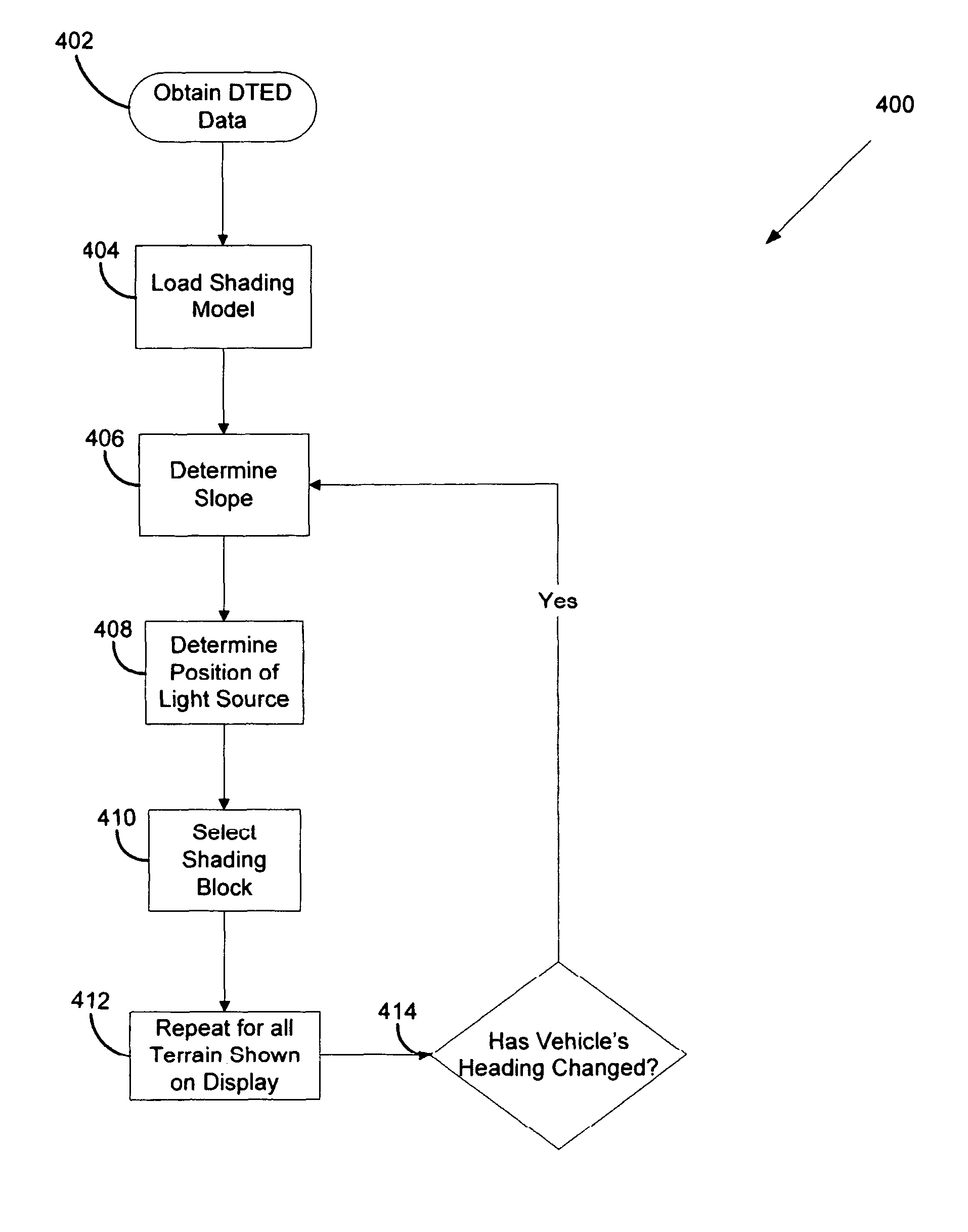
[0009]In some embodiments, a method for high-performance terrain rendering may include one or more of the following steps: (a) obtaining elevation data, (b) determining slope of a terrain surface, (c) selecting a sh

Problems solved by technology

This requires considerable computation resources for avionics systems where the light source moves dynamically with mid-flight heading changes.
The increased computational complexity adds to the cost and complexity of the system.

Method used


Image

  • Dynamic light shading in terrain rendering applications
  • Dynamic light shading in terrain rendering applications
  • Dynamic light shading in terrain rendering applications

Examples


Embodiment Construction

[0024]Reference will now be made in detail to embodiments of the invention, examples of which are illustrated in the accompanying drawings.

[0025]The following discussion is presented to enable a person skilled in the art to make and use the present teachings. Various modifications to the illustrated embodiments will be readily apparent to those skilled in the art, and the generic principles herein may be applied to other embodiments and applications without departing from the present teachings. Thus, the present teachings are not intended to be limited to embodiments shown, but are to be accorded the widest scope consistent with the principles and features disclosed herein. The following detailed description is to be read with reference to the figures, in which like elements in different figures have like reference numerals. The figures, which are not necessarily to scale, depict selected embodiments and are not intended to limit the scope of the present teachings. Skilled artisans ...


PUM


Abstract

In some embodiments, a method for high-performance terrain rendering may include one or more of the following steps: (a) obtaining elevation data, (b) determining slope of a terrain surface, (c) selecting a shading model to apply to the terrain surface based upon the slope of the terrain surface, (d) determining if a vehicle's heading has changed, and (e) aligning the shading model index based upon current heading.

Description

FIELD OF THE INVENTION[0001]Embodiments of the present invention relate to computer rendering. Particularly, embodiments of the present invention relate to computer rendering of terrain for most any vehicle. More particularly, embodiments of the present invention relate to dynamic light shading in high performance terrain rendering applications.BACKGROUND OF THE INVENTION[0002]Rendering is the process of generating an image from a model, by means of software programs or electronic hardware. The model is a description of three dimensional objects in a strictly defined language or data structure. The model may contain geometry, viewpoint, texture and shading information. The image, produced from rendering, is a digital image or raster graphics image. ‘Rendering’ is also used to describe the process of calculating effects in a video editing file to produce final video output.[0003]Rendering is one of the major sub-topics of 3D computer graphics, and in practice always connected to the ...

Claims


Application Information

Patent Timeline
IPC IPC(8): G06T15/50G06T15/60G09G5/02G09G5/00
CPCG06T15/80G06T17/05
Inventor HENDERSON, JAMES P.RUSSELL, JEFFREY D.ROHR, TOM C.
Owner ROCKWELL COLLINS INC
Learn More