Loudspeaker

a loudspeaker and speaker technology, applied in the field of loudspeakers, can solve the problems of further thinning of the loudspeaker, increase in etc., and achieve the effect of suppressing resonance in the longitudinal direction of the diaphragm, thinning the loudspeaker, and reducing the width of the tv s

Active Publication Date: 2011-10-04
PANASONIC CORP
View PDF16 Cites 14 Cited by
  • Summary
  • Abstract
  • Description
  • Claims
  • Application Information

AI Technical Summary

Benefits of technology

[0026]According to the present invention, an occurrence of a resonance mode can be suppressed without making a central part of a diaphragm in a dome shape. Therefore, a high-frequency limit of a loudspeaker can be extended, and slimming and thinning of the loudspeaker can be realized, whereas sound quality thereof is maintained. Specifically, according to a first invention, resonance in a longitudinal direction of the diaphragm can be suppressed, and primary resonance in a short axis direction of the diaphragm is also suppressed. Further, according to an eighth invention, the resonance in the longitudinal direction of the diaphragm can be suppressed, and the primary and secondary resonance in the short axis direction of the diaphragm is also suppressed.

Problems solved by technology

A loudspeaker device (hereinafter referred to as loudspeaker) for the television set is usually mounted on both sides of a CRT display, which results in an increase in width of the TV set.
Furthermore, since a thin-screen television using a plasma display or an LCD display is becoming popular, thinning of the loudspeaker is further required.

Method used


Image

  • Loudspeaker
  • Loudspeaker
  • Loudspeaker

Examples


embodiment 1

[0058]Hereinafter, a loudspeaker according to embodiment 1 of the present invention will be described. Note that, in FIGS. 1 to 20, component elements respectively having common functions are respectively given common numbers.

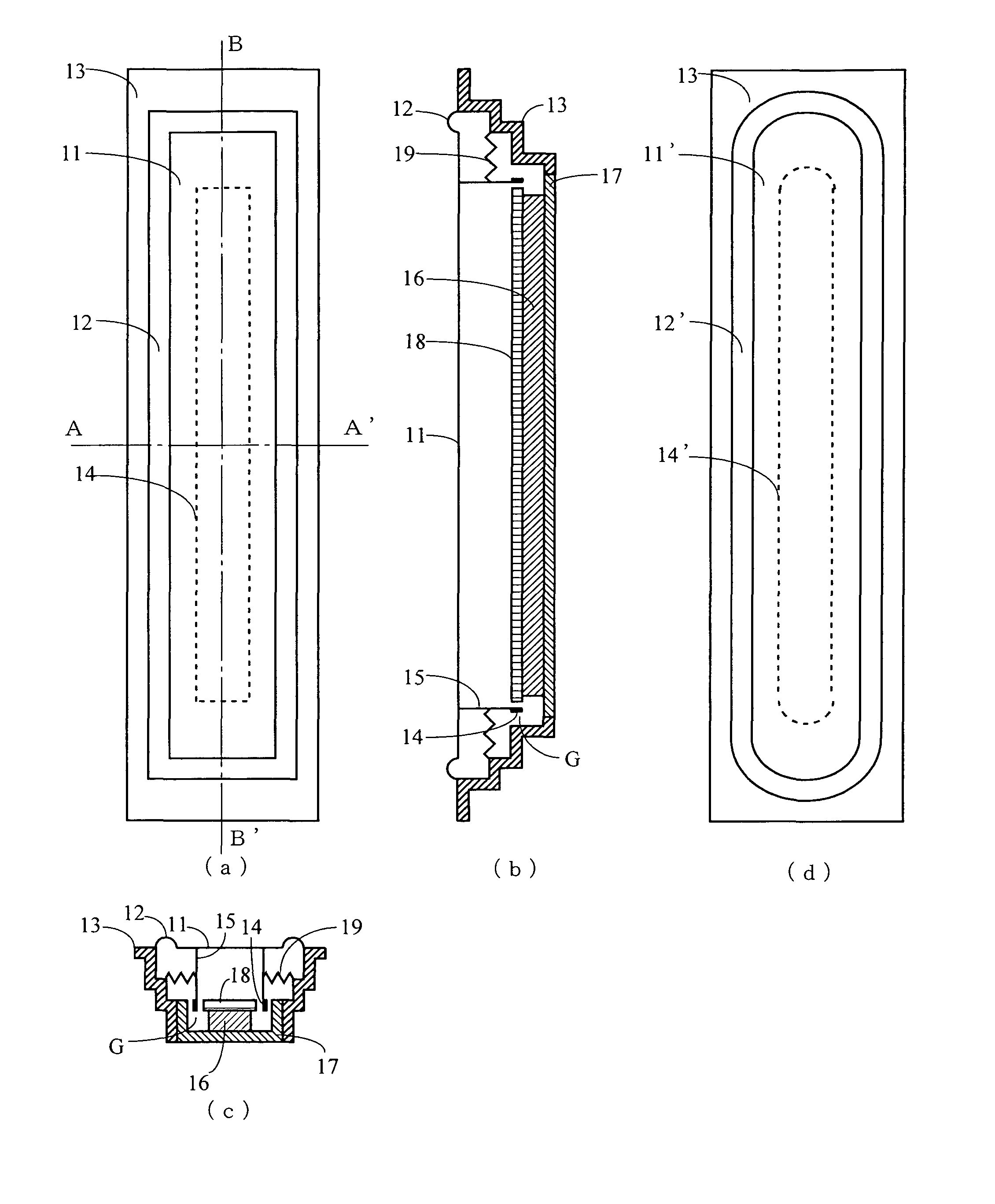
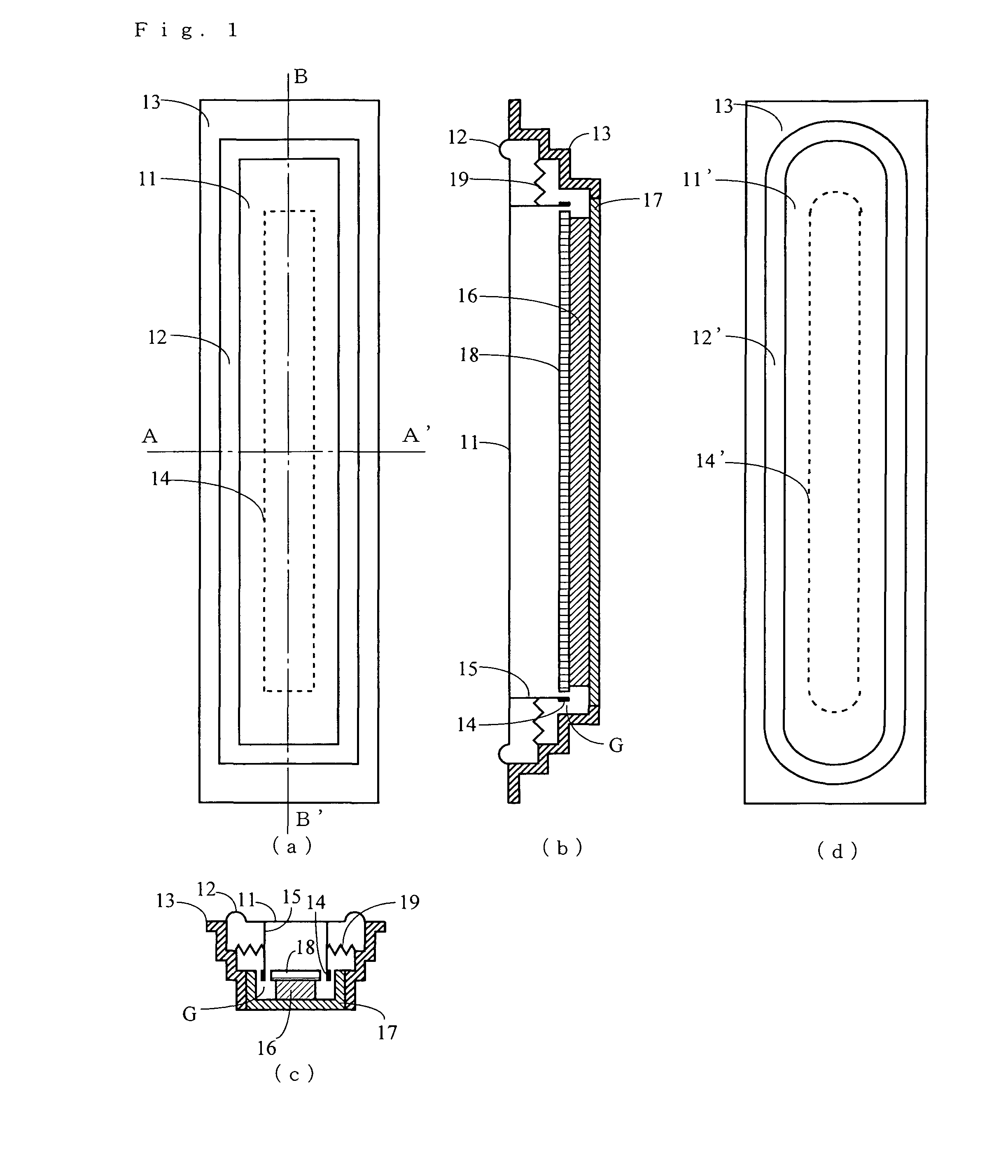
[0059]FIG. 1(a) is a plan view of the loudspeaker according to embodiment 1. FIG. 1(b) of a cross-sectional view (B-B′ cross-sectional view) in a longitudinal direction of the loudspeaker, and FIG. 1(c) is a cross-sectional view of a short axis direction (A-A′ cross-sectional view) of the loudspeaker. Further, FIG. 1(d) is a plan view showing a diagram having a different shape. The loudspeaker comprises a diaphragm 11, an edge 12, a frame 13, a voice coil 14, a voice coil bobbin 15, a magnet 16, a yoke 17, a top plate 18, and a suspension 19. The loudspeaker is of an elongated shape having a longitudinal direction and a short axis direction, lengths of which are different from each other.

[0060]In FIGS. 1(a) to (c), the diaphragm 11 has a rectangular planar shap...

embodiment 2

[0078]Hereinafter, a loudspeaker according to embodiment 2 will be described. FIG. 10(a) is a plan view showing the loudspeaker of embodiment 2, FIG. 10(b) is a cross-sectional view (B-B′ cross-sectional view) of a long side of the loudspeaker, and FIG. 10(c) is a cross-sectional view (A-A′ cross-sectional view) of a short side of the loudspeaker. FIG. 10(d) is a partially enlarged view of a region P shown in FIG. 10(b). With respect to (a) to (d) of FIG. 10, component elements respectively having identical functions to the component elements shown in (a) to (d) of FIG. 1 are respectively provided common reference characters. The loudspeaker according to embodiment 2 is different, in that a voice coil 14 thereof is directly connected to a diaphragm 11 thereof, from the loudspeaker according to embodiment 1. Further, the loudspeaker according to embodiment 2 has a magnetic circuit without a top plate 18, which is different from the loudspeaker according to embodiment 1.

[0079]As shown...

embodiment 3

[0083]Hereinafter, a loudspeaker according to embodiment 3 will be described. FIG. 11(a) is a plan view showing the loudspeaker, FIG. 11(b) is a cross-sectional view (B-B′ cross-sectional view) of a long side of the loudspeaker, and FIG. 11(c) is a cross-sectional view (A-A′ cross-sectional view) of a short side of the loudspeaker. FIG. 11(d) is a partially enlarged view of a region P shown in FIG. 11(b). Further, FIG. 11(e) is a diagram showing a different shape of a voice coil. Note that, in (a) to (c) of FIG. 11, component elements respectively having identical functions to the component elements shown in (a) to (d) of FIG. 1 are respectively provided common reference characters. The loudspeaker according to embodiment 3 is different, in that a voice coil14 thereof is a printed coil, from the loudspeaker according to embodiment 2.

[0084]As shown in (a) to (c) of FIG. 11, an outer circumference of a diaphragm 11 is firmly fixed to an inner circumference side of an edge 12 having an...


PUM


Abstract

A loudspeaker comprises a diaphragm, an edge operable to support, on a frame, the diaphragm in such a manner that enables vibration thereof, and a voice coil operable to generate a driving force. The voice coil is of an approximate rectangular shape, and a length of a long axis direction of the voice coil is no less than 60% of a length of a long axis direction of the diaphragm. Positions of long sides of the voice coil to be fixed on the diaphragm are positions corresponding to nodes of a primary resonance mode in a short axis direction of the diaphragm, or in the respective vicinities thereof. Accordingly, it is possible to realize a high sound quality loudspeaker having a narrow width (elongated structure), but not easily causing resonance, thereby obtaining a flat frequency characteristic.

Description

TECHNICAL FIELD[0001]The present invention relates to a loudspeaker, more particularly to a loudspeaker which is improved in slimness and thinness.BACKGROUND ART[0002]In recent years, a horizontally long television screen is becoming popular due to spread of so-called high definition and wide vision televisions. On the other hand, in consideration of Japanese housing circumstances, a television set which is narrow in width and thin in depth on the whole is desired.[0003]A loudspeaker device (hereinafter referred to as loudspeaker) for the television set is usually mounted on both sides of a CRT display, which results in an increase in width of the TV set. Therefore, the loudspeaker having an elongated structure such as a square type, an elliptic type and the like has traditionally been used for the television set. Further, since the CRT display is lengthened horizontally, the width of the loudspeaker requires to be further narrowed down. Further, high quality in sound comparable to ...

Claims


Application Information

Patent Timeline
Patent Type & Authority Patents(United States)
IPC IPC(8): H04R1/00H04R9/06H04R11/02H04R7/04H04R7/20
CPCH04R7/04H04R9/06H04R2209/041
Inventor TAKEWA, HIROYUKI
Owner PANASONIC CORP
Why Eureka
Try Eureka