
Stair system

a stair system and stair tread technology, applied in the field of stair systems, can solve the problems of unnecessarily complicated assembly process, unfavorable free-floating of treads and risers, complex system that requires many additional components, etc., and achieve the effect of efficient assembly process and minimal components of the stair system

Inactive Publication Date: 2011-10-11
WON YONG HWAN
View PDF23 Cites 9 Cited by
  • Summary
  • Abstract
  • Description
  • Claims
  • Application Information

AI Technical Summary

Benefits of technology

[0012]According to principles of this invention, a stair system is provided that minimizes the components of the stair system and provides an efficient assembly process by allowing flexibility in the placement of the riser(s). The stair system includes a tread, the tread having a substantially planar body portion, a stair nose portion located at one side of the planar body portion, a dado located behind the stair nose portion, and a first plurality of grooves located at a side opposite the stair nose portion, a first riser having a substantially planar body portion, the first riser being received in one of the plurality of grooves, and a second riser having a substantially planar body portion, the second riser being received in the dado of the tread.

Problems solved by technology

However, they are unattractive in that the stair nose is higher than the tread because of the overlapping arrangement.
The second system does allow the tread and stair nose to be coplanar, but because they are joined by the tongue and groove, the system does not allow the tread and risers to be free-floating.
However, U.S. Pat. No. 6,115,975 is a complicated system that requires many additional components.
As a result the assembly process is unnecessarily complicated.

Method used


Image

  • Stair system
  • Stair system
  • Stair system

Examples


Embodiment Construction

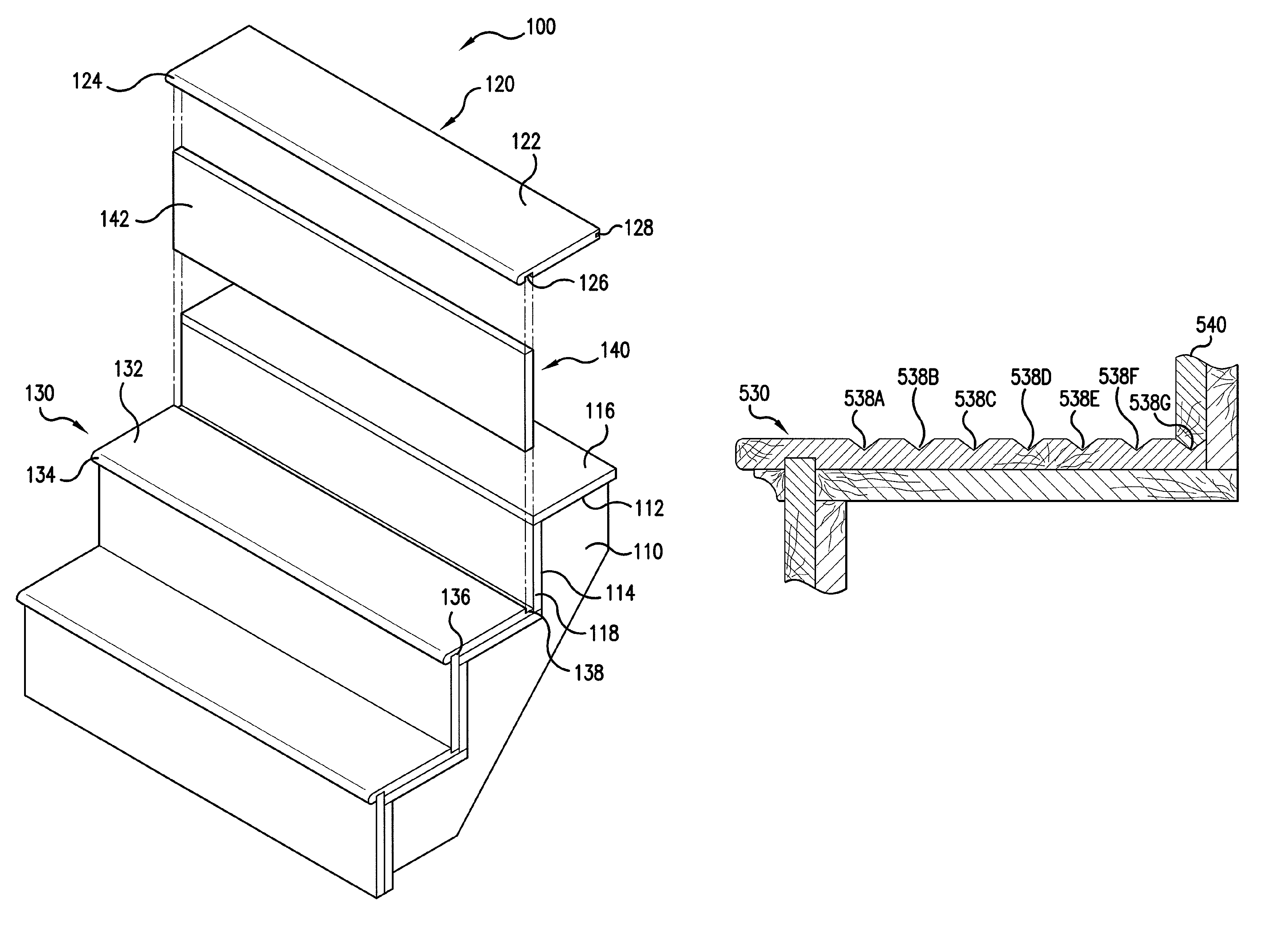
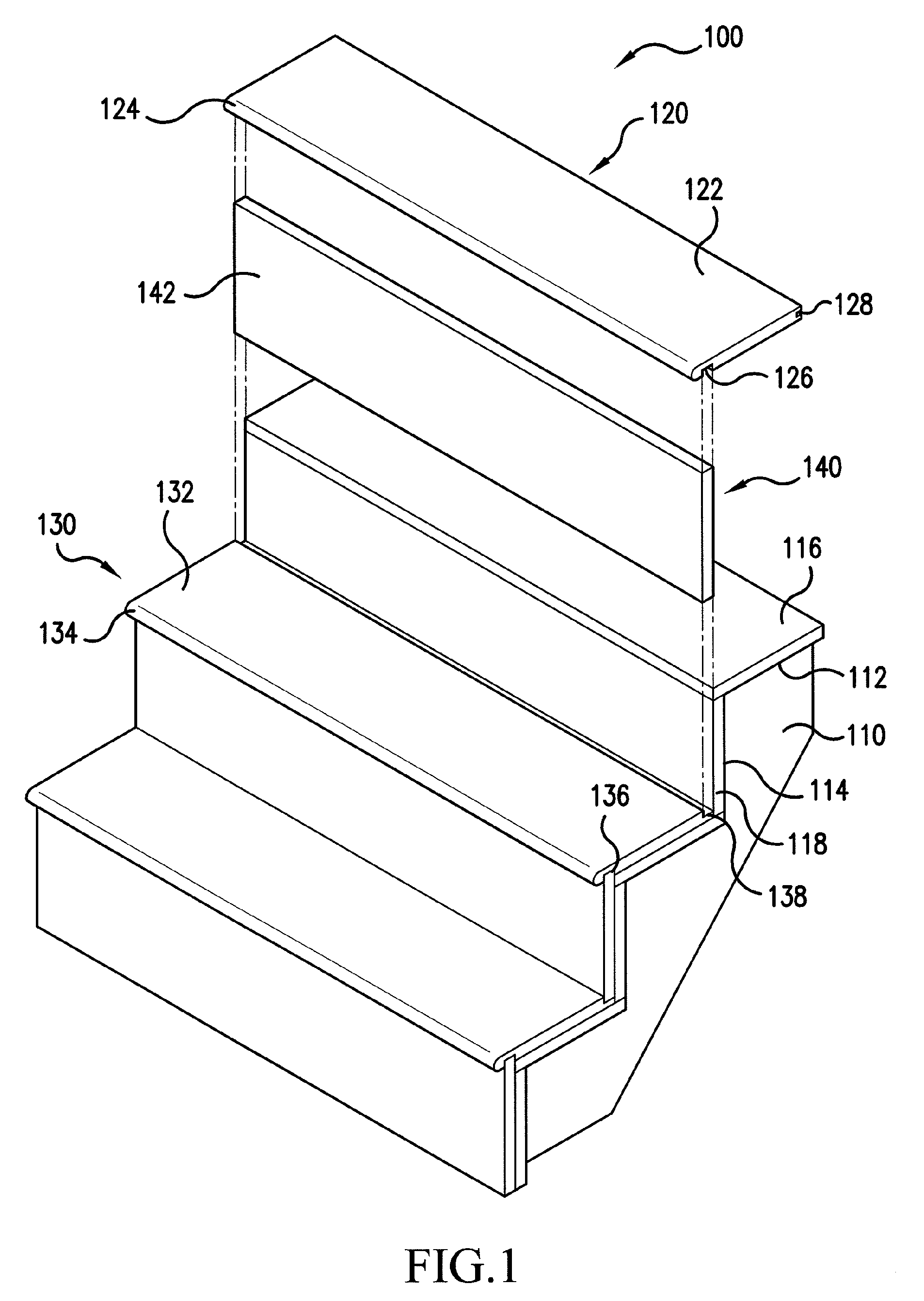
[0038]Referring to FIG. 1, the stair system 100 according to the first exemplary embodiment includes conventional stringers 110 (one shown), each stringer 110 provides a plurality of tread sides 112 and a plurality of riser sides 114 formed therein. A tread sub flooring 116 spans between corresponding tread sides 112 and a riser sub flooring 118 spans between corresponding riser side 114. The stringers 110, tread sub floorings 116, and riser sub floorings 118 are assembled using conventional techniques including fasteners and / or adhesives.

[0039]The stair system 100 includes at least two different treads depending on the location of the tread. As shown in FIG. 1, the uppermost tread or top tread 120 has a planar body portion 122 and a stair nose portion 124. A dado 126 is provided behind the stair nose portion 124 and extends along the length of the planar body portion 122. As shown in FIG. 1, the stair nose portion 124 may have a thickness equal to the planar body portion 122, altho...


PUM


Abstract

A stair system including an upper tread having a substantially planar body portion, a stair nose portion located at one side of the planar body portion, and a dado located behind the stair nose portion, at least one lower tread, the lower tread having a substantially planar body portion, a stair nose portion located at one side of the planar body portion, a dado located behind the stair nose portion, and a groove located at a side opposite the stair nose portion, and at least two risers, each riser having a substantially planar body portion. In the stair system, one of the at least two risers is receivable between the dado of the upper tread and the groove of the lower tread and the other of the at least two risers is receivable in the dado of the lower tread.

Description

CROSS-REFERENCE TO RELATED APPLICATIONS[0001]This application is continuation-in-part of prior application Ser. No. 12 / 007,211, filed Jan. 8, 2008, now abandoned, and is a continuation-in-part application of prior application Ser. No. 11 / 714,774, filed Mar. 7, 2007, now abandoned, all of which are herein incorporated by reference in their entireties.BACKGROUND OF THE INVENTION[0002]1. Field of the Invention[0003]The present invention is generally directed to a stair system, and more particularly to modular treads and risers of a stair system.[0004]2. Description of Related Art[0005]Generally, stair systems having nose moldings have been constructed in a similar manner using the same basic methods. For example, most stair systems employ a plurality of stringers having tread sides cut out, on which are secured tread sub flooring that span between the stringers. The stringers also have riser sides cut out, on which are secured riser sub floorings that also span between the stringers. D...

Claims


Application Information

Patent Timeline
Patent Type & Authority Patents(United States)
IPC IPC(8): E04F11/00
CPCE04F11/02E04F11/108E04F11/16
Inventor WON, YONG HWAN
Owner WON YONG HWAN
Learn More