Brake disk lock having a tilted locking bolt

a locking bolt and brake disk technology, applied in the field of brake disk locks, can solve the problems of inconvenient manufacture and complex structure of such brake disk locks, and achieve the effects of simple operation, improved security, and simplified construction

Inactive Publication Date: 2011-10-18
ABUS AUGUST BREMICKER SOEHNE AG
View PDF17 Cites 3 Cited by
  • Summary
  • Abstract
  • Description
  • Claims
  • Application Information

AI Technical Summary

Benefits of technology

[0006]It is an object of the invention to provide a brake disk lock with improved security against being broken open, in particular with respect to a spreading apart or prizing open of the housing sections by action of a chisel or the like, wherein the brake disk lock should have a simplified construction. The brake disk lock should further be simple to operate.
[0009]As a result, high security against being broken open is achieved, with simultaneously a simple structure of the brake disk lock being possible. A so-called automatic function can in particular be realized—as will be explained in the following—so that the brake disk lock in accordance with the invention is additionally characterized by a simplified handling.
[0012]It is furthermore of advantage if the engagement opening of the second housing section receives the locking bolt in a substantially shaped-matched manner. In other words, the second housing section should surround the locking bolt end introduced into the engagement opening substantially a really at the periphery. A particularly effective wedging of the locking bolt at the second housing section is also hereby achieved in the case of a breaking open attempt of the explained kind.
[0013]It is furthermore preferred if the locking bolt is made cylindrical (with respect to its closed position) at least in the region of the receiving gap of the lock body and of the engagement opening of the second housing section, i.e. the locking bolt is elongated with a round cross-section along a longitudinal axis (with a varying cross-section also being able to be provided along the longitudinal axis). The locking bolt can hereby have a particularly simple structure and the associated engagement opening can also be made as a simple cylindrical bore (with the axis of the bore being aligned obliquely to the receiving gap in accordance with the inclination of the locking bolt.
[0014]In accordance with a further advantageous embodiment, a latch can furthermore be provided at the first housing section and is movable along a latching direction from an unlatched position into a latched position to latch the locking bolt in the locked position. A particularly compact structure of the first housing section and thus of the lock body as well as a simple accessibility of a lock cylinder cooperating with the latch are achieved when the latching direction of the latch is aligned obliquely to the named closing direction of the locking bolt. In this respect, the latching direction of the latch can be aligned obliquely or parallel to the direction of extent of the receiving gap of the lock body.

Problems solved by technology

Whereas such a design has proved itself in practice, the structure and the manufacture of such a brake disk lock are undesirably complex and / or expensive.

Method used


Image

  • Brake disk lock having a tilted locking bolt
  • Brake disk lock having a tilted locking bolt
  • Brake disk lock having a tilted locking bolt

Examples


Embodiment Construction

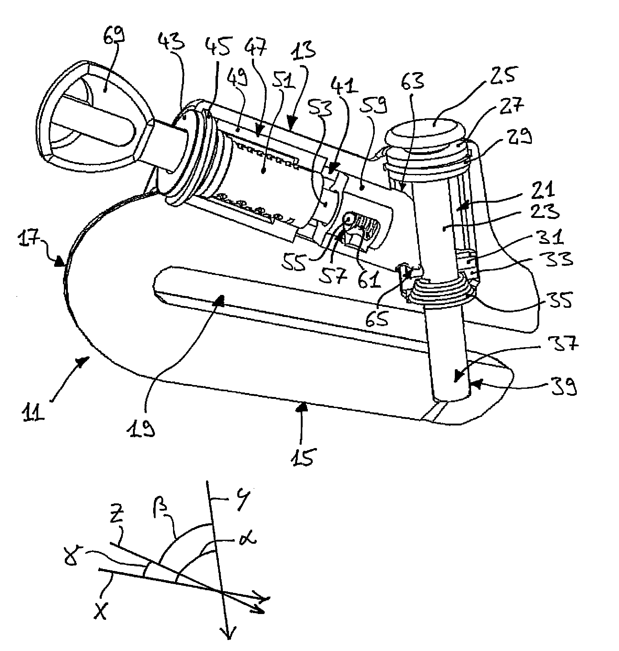
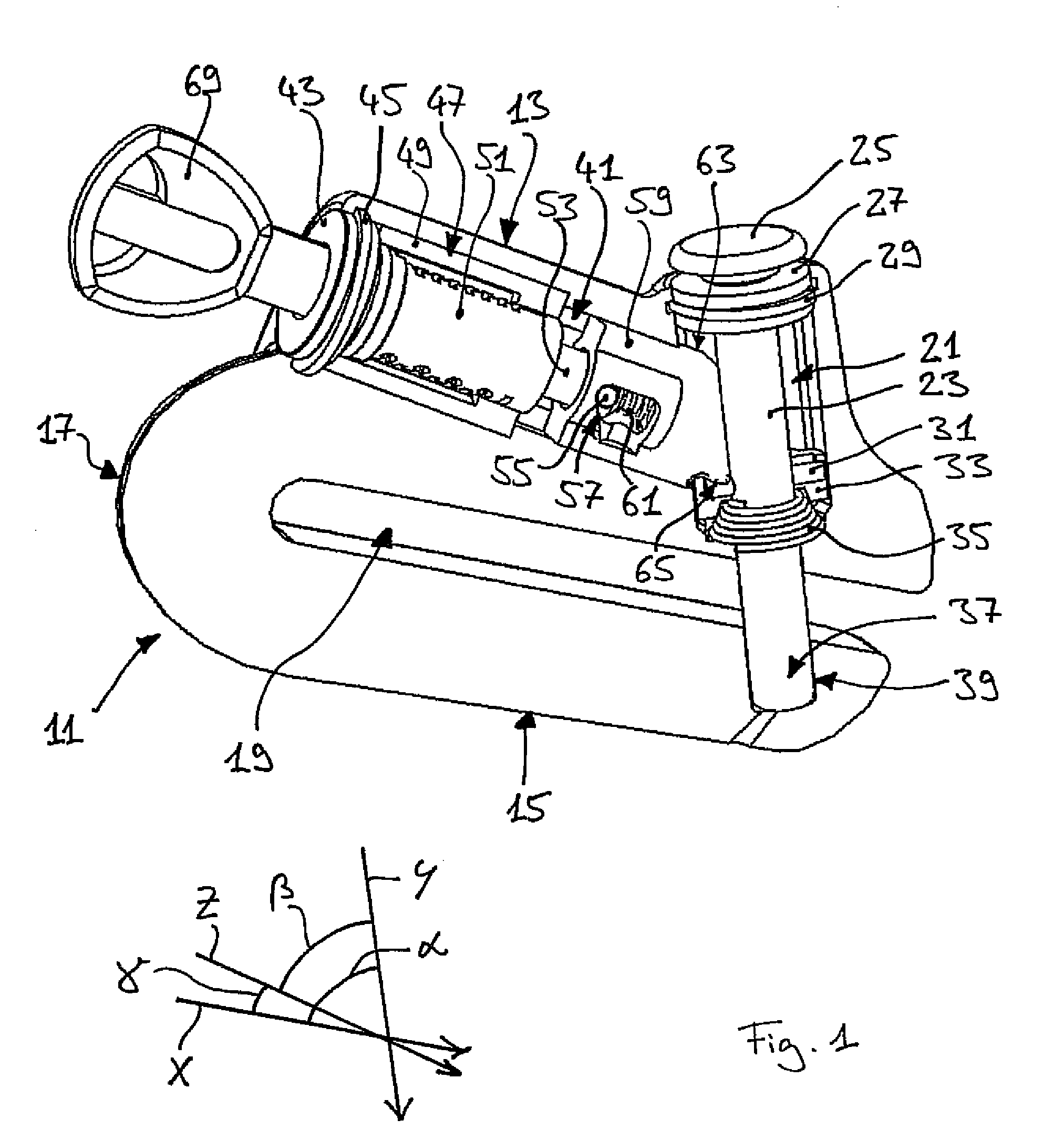
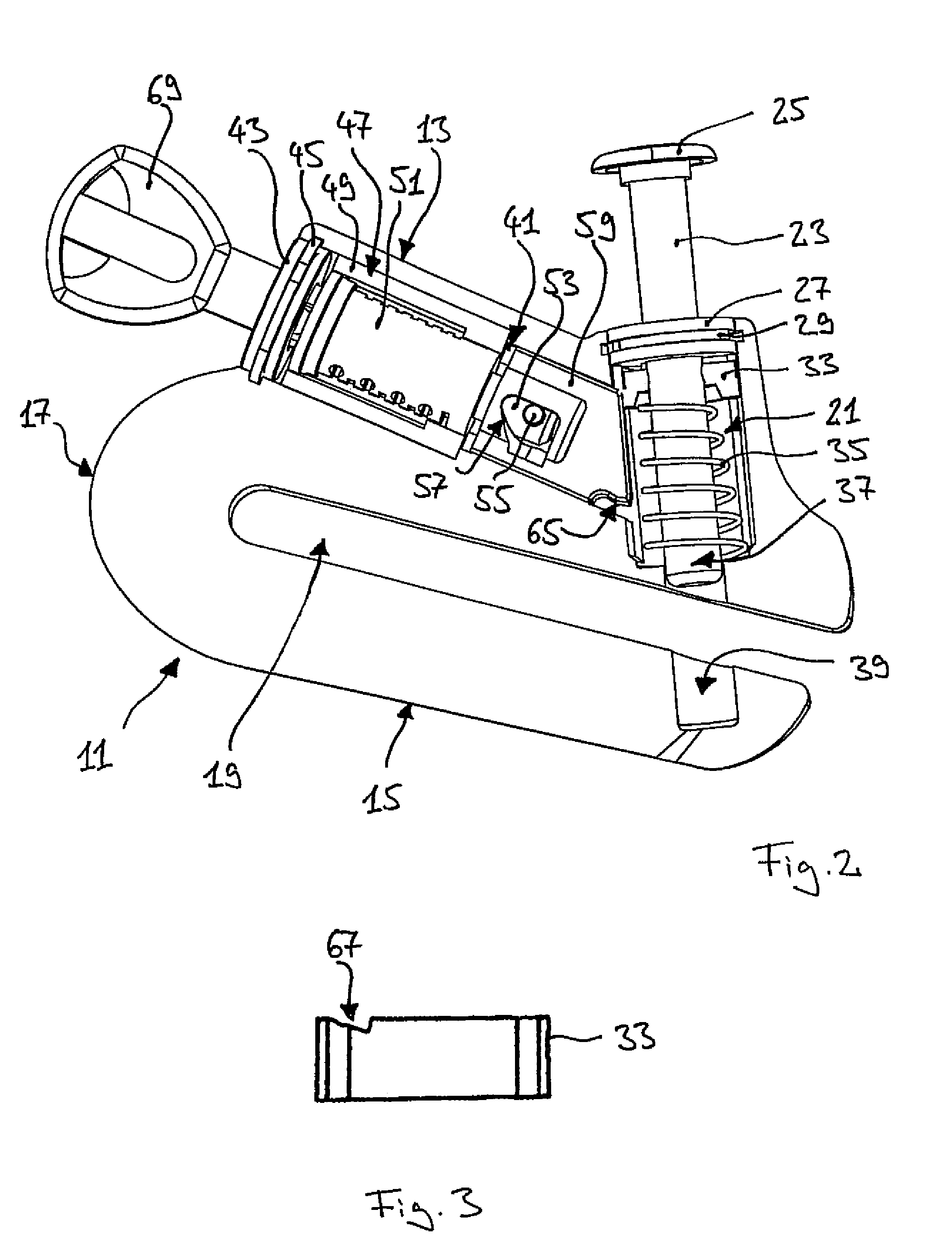
[0021]The brake disk lock shown in the Figures can be fixed to a brake disk of a motorcycle or the like to secure it against unauthorized use. For this purpose, the brake disk lock has a lock body 11 of metal. The lock body 11 includes a first housing section 13 and a second housing section 15 which are connected to one another in one piece via a connection section 17 and which bound a receiving gap 19 for the reception of a brake disk in a substantially U-shaped arrangement. The receiving gap 19 extends in a straight line along a direction of extent X between the two housing sections 13, 15.

[0022]A locking bolt passage 21 is formed at the first housing section and a locking bolt 23 is supported axially movable in it. The locking bolt 23 is made of metal and is substantially cylindrical, i.e. it extends in a straight line and has a round cross-section. The locking bolt 23 has an actuating cap 25 projecting out of the lock body 11 at the end remote from the second housing section 15....


PUM


Abstract

A brake disk lock having a lock body which has a first housing section and a second housing section which bound a receiving gap for the reception of a brake disk in a typically U-shaped arrangement. A locking bolt is provided at the first housing section and is movable along a closing direction from a release position into a closed position. In the closed position, the locking bolt engages into an engagement opening of the second housing section and closes the receiving gap. The closing direction of the locking bolt is aligned obliquely to the receiving gap of the lock body at an angle different from 90°.

Description

CROSS-REFERENCE TO RELATED APPLICATION[0001]This application claims priority of German Patent Application 10 2009 030 033.3 filed Jun. 23, 2009.FIELD OF THE INVENTION[0002]The invention relates to a brake disk lock having a lock body which has a first housing section and a second housing section which bound a receiving gap for the reception of a brake disk in a typically U-shaped arrangement. A locking bolt is provided at the first housing section and is movable along a closing direction from a release position into a closed position. In the closed position, the locking bolt engages into an engagement opening of the second housing section and closes the receiving gap.BACKGROUND OF THE INVENTION[0003]Such a brake disk lock serves for the securing of, for example, a motorcycle, a motor scooter or a quad bike against unauthorized use. For this purpose, the lock is applied to a brake disk of the parked vehicle such that the brake disk projects into the receiving gap formed by the housin...

Claims


Application Information

Patent Timeline
Patent Type & Authority Patents(United States)
IPC IPC(8): E05B67/36
CPCB62H5/18Y10T70/441Y10T70/5872Y10T70/585
Inventor NG, HOI JARMNG, LEGAL REPRESENTATIVE, WAI LEUNGVESTMAN, KAJ
Owner ABUS AUGUST BREMICKER SOEHNE AG
Why Eureka
Try Eureka