Quick connect thermocouple mounting device and associated method of use

a technology of thermocouple mounting and quick connection, which is applied in the direction of instruments, heat measurement, lighting and heating apparatus, etc., can solve the problems of increasing costs, requiring additional labor, and affecting the safety of users, so as to prevent accidental disengagement and reduce manufacturing costs

Inactive Publication Date: 2011-10-18
ROBERTSHAW CONTROLS CO
View PDF25 Cites 6 Cited by
  • Summary
  • Abstract
  • Description
  • Claims
  • Application Information

AI Technical Summary

Benefits of technology

A thermocouple mounting assembly is provided. The mounting assembly includes a first retainer for mounting to a body such as a fuel control unit. The first retainer has an internal chamber and first and second ends with openings therein. The first end opening provides access to the chamber to provide exposure for a thermocouple portion to contact or be positioned adjacent to a member for operation of the thermocouple control system. A second end opening provides access to the chamber for a second retainer to extend through and to releasably secure a thermocouple portion within the chamber. The interior of the chamber contains a securement device to cooperatively interengage with a second securement device on the second retainer to form a bayonet mounting arrangement between the first and second retainers with the interengaging portions being shielded from external contact. The bayonet mounting arrangement releasably secures a thermocouple portion within the chamber. The bayonet mounting arrangement is constructed to prevent accidental disengagement of the second retainer from the first retainer. Preferably the mounting assembly and retainer components are molded and not machined to significantly reduce manufacturing costs.

Problems solved by technology

While generally effective, such known thermocouple mounts have significant drawbacks.
They require a combination of various parts which increase costs and necessitates additional labor to make an assembly or to effect mounting of the thermocouple.
Thermocouple mounts also, at times, requires a certain level of dimensional precision in order to ensure proper operation which can also increase costs, both for the product itself and the additional labor to effect proper assembly and testing to ensure proper operation.
When used with fuel control units, for example, the female receptacle is complex and expensive to manufacture as disclosed in U.S. Pat. No. 6,010,327.
Usually, such receptacles are made of relatively soft material and are easily damaged by cross threading, a tightening tool, dropping, and the like.
While the push in-type thermocouple coupling device disclosed in U.S. Pat. No. 6,010,327 is effective, it is relatively expensive and difficult to affect a repair of the thermocouple system.
Screw in-type thermocouple mounts may also be damaged on the wrench flats during installation and are at times difficult to loosen which may also damage the shank particularly when the shank is made of a soft material.
However, screw in-type shanks reduce the probability of accidental dislodgement of the thermocouple mounts from its desired monitoring position.
When the thermocouple mounts extend out of the bottom of the unit when installed, repair is difficult because of the upside down orientation.
Machining of a thermocouple retainer such as that shown in U.S. Pat. No. 6,010,327 is complex and expensive.

Method used


Image

  • Quick connect thermocouple mounting device and associated method of use
  • Quick connect thermocouple mounting device and associated method of use
  • Quick connect thermocouple mounting device and associated method of use

Examples


Embodiment Construction

In the following detailed description, numerous specific aspects are set forth in order to provide a thorough understanding of the invention. However, it will be understood by those skilled in the art that the present invention may be practiced without these specific details. In other instances, well-known methods, procedures and components have not been described in detail so as to obscure the present invention.

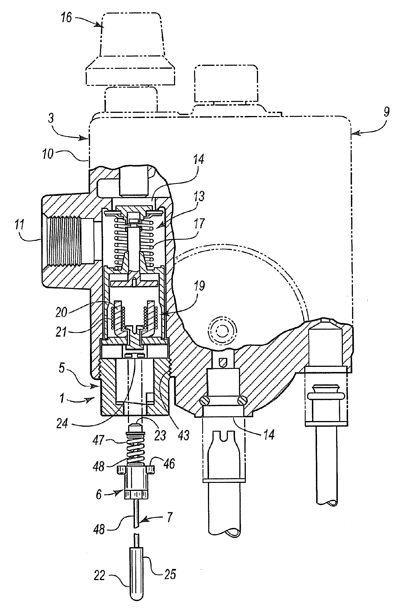
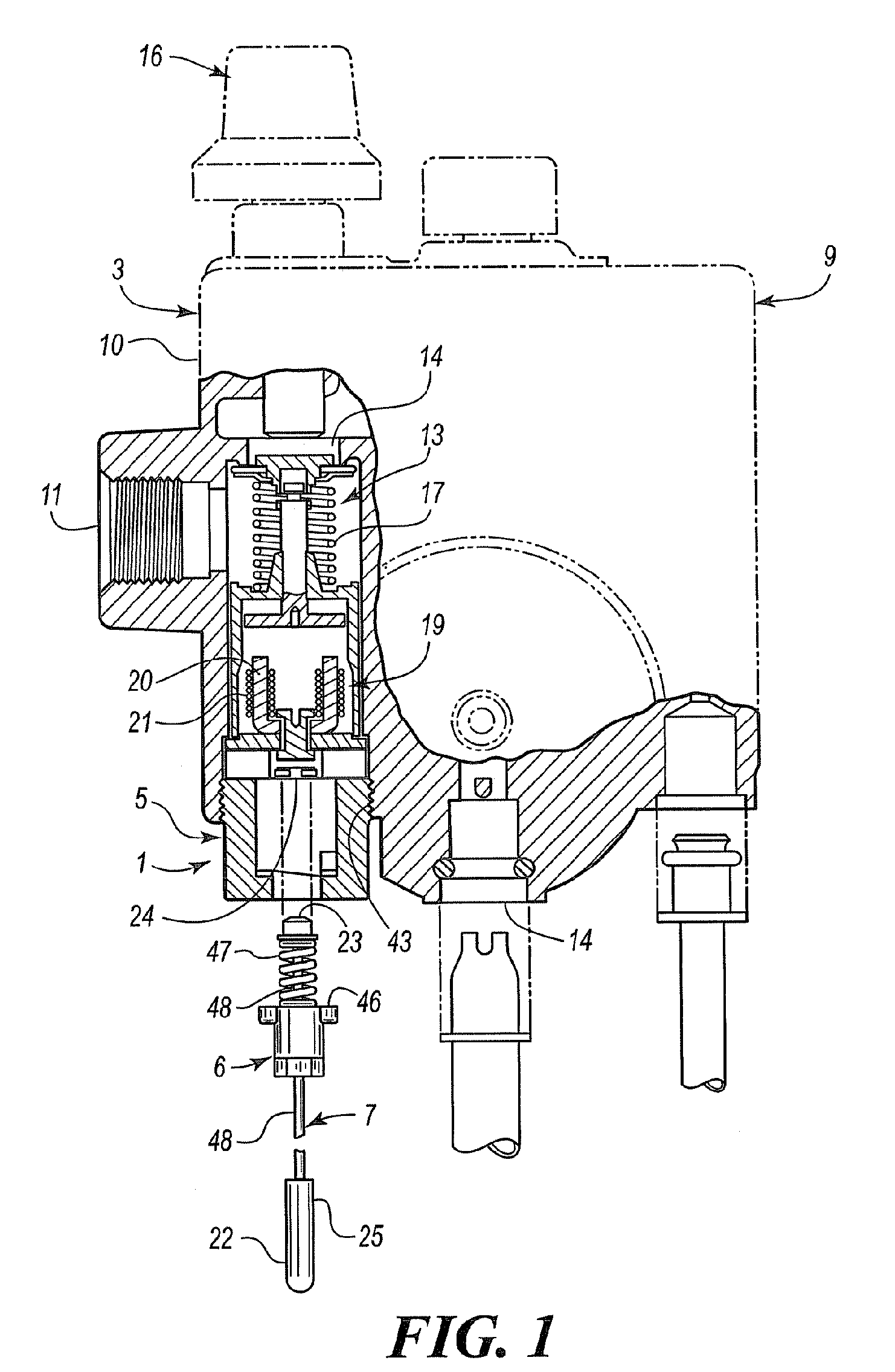
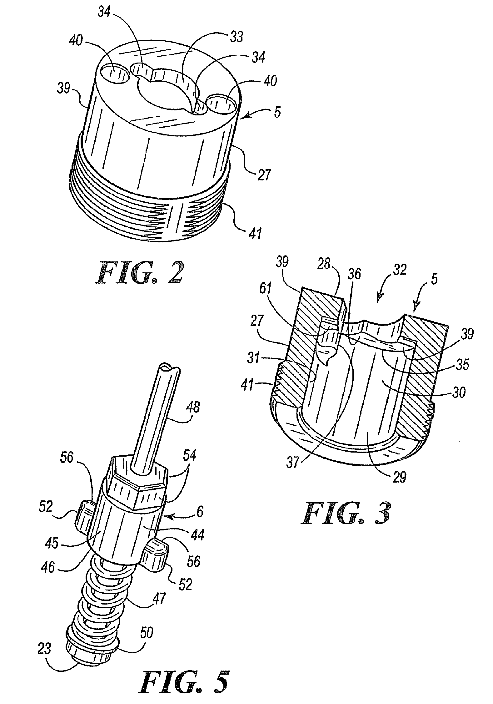
A thermocouple mounting assembly that is adapted for mounting to a body 3 is generally indicated by numeral 1. The mounting assembly 1 includes retainers indicated by numerals 5 and 6. The thermocouple assembly 7 is adapted to be mounted to the body 3 by interengagement of portions of the retainers 5 and 6 forming a shielded bayonet mounting arrangement. The thermocouple mounting assembly 1, including retainer 5 and / or retainer 6, is preferably molded. This can include any of a wide variety of metal molding processes, including but is not limited to, die casting and investme...


PUM


Abstract

A thermocouple mounting assembly is provided. A plurality of retainers includes portions that are interengageable, some portions carried by a body and some portions carried by a thermocouple assembly to effect releasable mounting of a thermocouple assembly to a body. The retainers are constructed and shaped to provide for their formation by a molding process such as die-casting or investment casting, eliminating or substantially eliminating the need for machining of the retainer components. Preferably, there is an audible sound, e.g., click, present to signify when the retainers are interengaged.

Description

BACKGROUND OF THE INVENTIONThermocouple mounting devices are well known in the industry. One common type of mounting device is a bayonet mount. This type of mounting device utilizes a cap with one or more L-shaped slots. The cap is mounted to the thermocouple. The cap is received over an end of a shank, which has at least one radially outwardly extending pin that is received within the L-shaped slot. The shank is generally mounted to an object that is to monitor temperature. Spring tension is applied to maintain that the cap and the shank are interlocked. A second type of connection is a screw in device, that is simply a threaded shank which includes the thermocouple extend therethrough. The shank is threadably received in a threaded receptacle or well. Wrench flats may be provided at one end of the shank for use of a wrench to position the thermocouple in connection with a contact surface found in the receptacle.A third type of thermocouple mounting device can be found in U.S. Pat....

Claims


Application Information

Patent Timeline
Patent Type & Authority Patents(United States)
IPC IPC(8): H01L35/02
CPCF23N5/107G01K7/023F23N2035/14F23N2900/05005F23N2900/05101F23N2235/14
Inventor NGUYEN, CAN TRONG
Owner ROBERTSHAW CONTROLS CO
Why Eureka
Try Eureka