
System and method for virtual control of laboratory equipment

a laboratory equipment and virtual control technology, applied in the field of laboratory equipment, can solve the problems of inability to collaborate with remote users, short-range connections to general-purpose computer systems, and difficulty in collaboration with remote users

Inactive Publication Date: 2011-10-18
INT BUSINESS MASCH CORP
View PDF9 Cites 21 Cited by
  • Summary
  • Abstract
  • Description
  • Claims
  • Application Information

AI Technical Summary

Problems solved by technology

While the rack mounting system provides an effective approach for users to interact with the laboratory equipment, collaboration with remote users may be difficult as remote users lack the ability to interact with the display components and control keys of the laboratory equipment.
However, these connections to general-purpose computer systems are short-ranged and the problem of allowing for collaboration with remote users is not solved by the ability to control the laboratory equipment using local computer systems.
However, this process may be time consuming, tedious and may require programming skills on the part of the user.

Method used

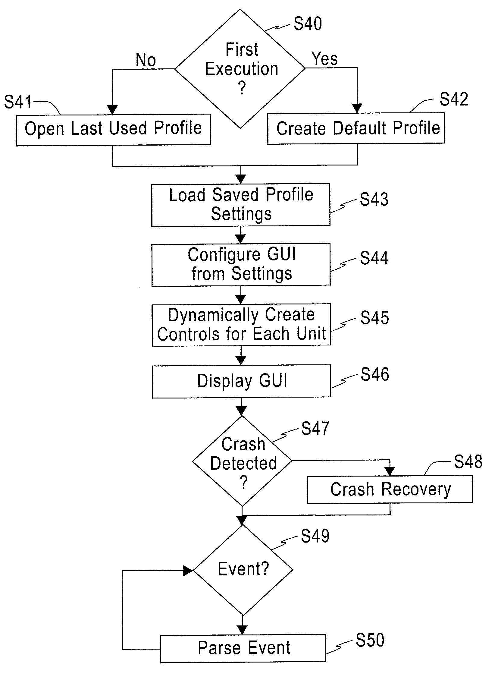

Image

  • System and method for virtual control of laboratory equipment
  • System and method for virtual control of laboratory equipment
  • System and method for virtual control of laboratory equipment

Examples


Embodiment Construction

[0025]In describing exemplary embodiments of the present disclosure illustrated in the drawings, specific terminology is employed for sake of clarity. However, the present disclosure is not intended to be limited to the specific terminology so selected, and it is to be understood that each specific element includes all technical equivalents which operate in a similar manner.

[0026]Exemplary embodiments of the present invention seek to provide a system and method for the remote control of laboratory equipment using an advanced user interface so that control of the laboratory equipment may be quick, efficient, simple, and does not require the user to possess computer programming skills. Accordingly, collaboration between local and remote users may be facilitated.

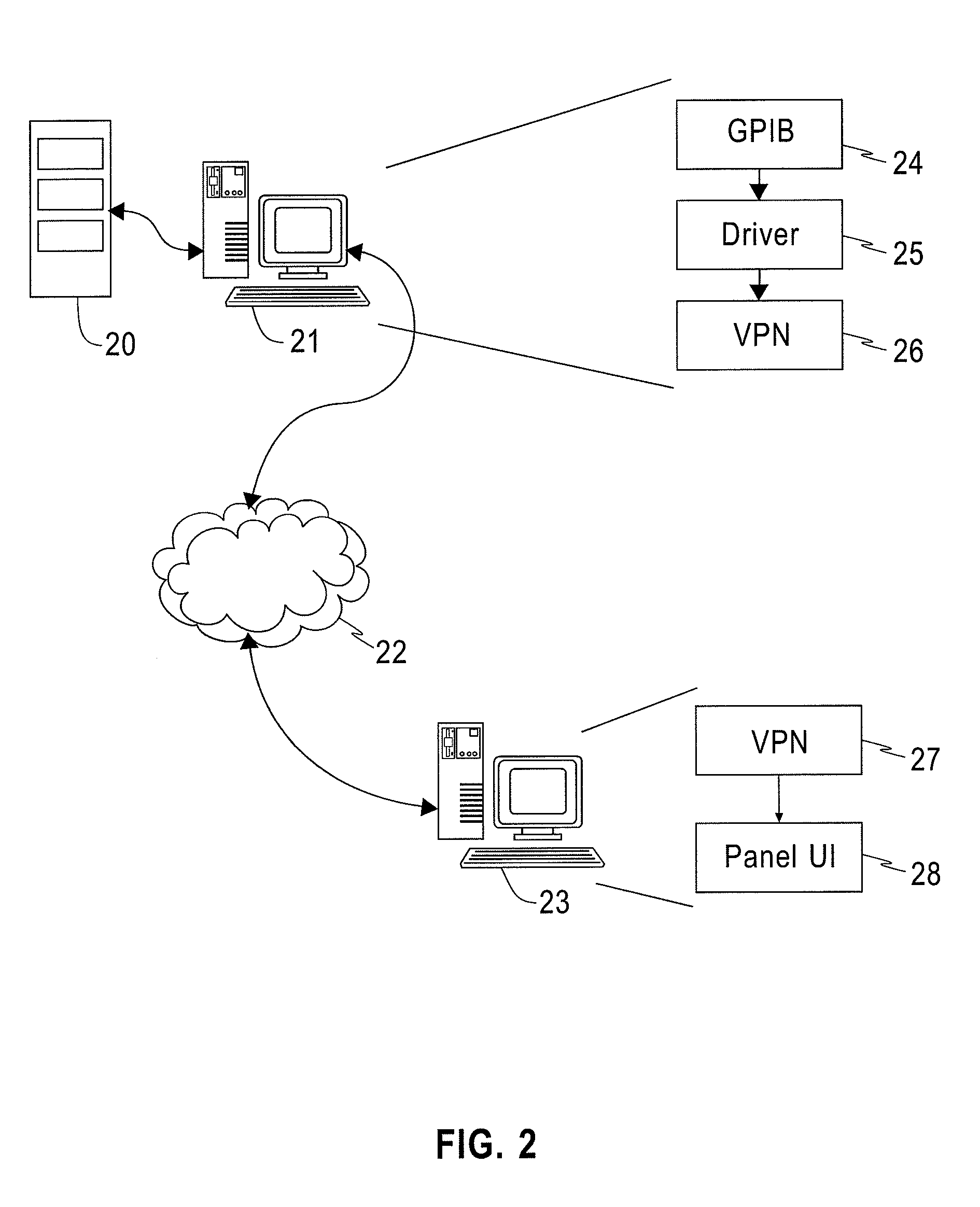
[0027]FIG. 2 is a schematic representation of a system for providing remote control of laboratory equipment according to an exemplary embodiment of the present invention. Laboratory equipment 20 may be connected to a general pu...


PUM


Abstract

A system for virtual control of electronic laboratory equipment includes a local computer system. One or more items of electronic laboratory equipment are connected to the local computer system. Each item of electronic laboratory equipment has a physical control panel including one or more displays or controls. A virtual control panel generation unit generates a virtual control panel accessible from a remote computer system. The virtual control panel is substantially similar to the physical control panel in appearance. A command interpretation unit monitors interaction between the remote user and the virtual control panel and generates electronic laboratory equipment commands for exploiting the functionality of the electronic laboratory equipment.

Description

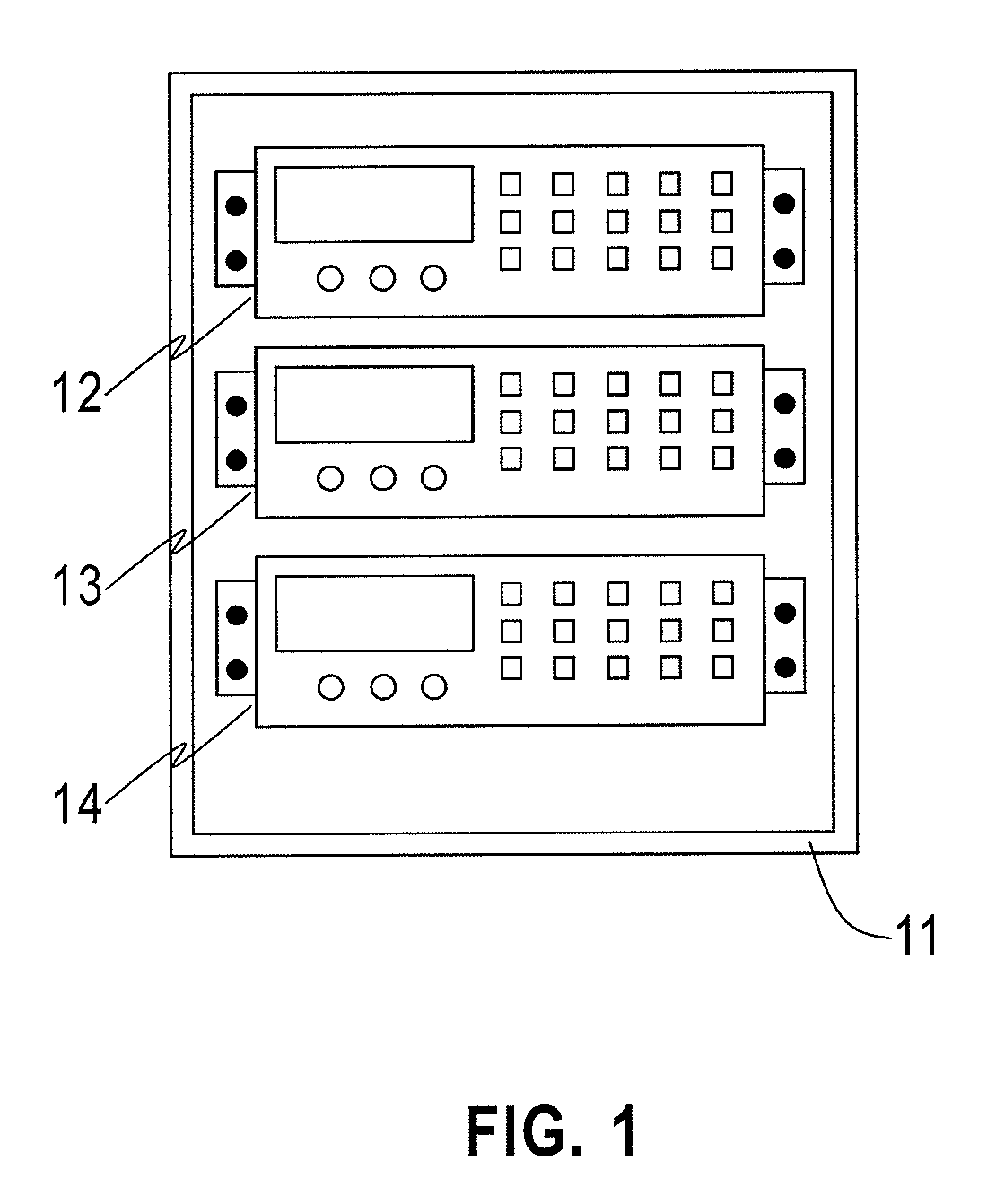
BACKGROUND[0001]1. Technical Field[0002]The present disclosure relates to laboratory equipment and, more specifically, to a system and method for the virtual control of laboratory equipment.[0003]2. Discussion of Related Art[0004]Electronic laboratory equipment such as power supplies, signal generators, sensors, and the like are common fixtures in modern laboratories. Each piece of equipment may feature one or more display components and one or more control keys. Signal inputs and outputs of the equipment may be connected to various pieces of hardware to perform various tests.[0005]As a laboratory might have a large number of such items of test equipment, the test equipment may be rack-mounted for efficient storage and use. When rack-mounted, the items of test equipment are stacked in a shelf-like configuration, with all display components and control keys located on the front face of the equipment. Input and output cable connectors may be located either on the front face or the bac...

Claims


Application Information

Patent Timeline
Patent Type & Authority Patents(United States)
IPC IPC(8): G05B19/18
CPCG05B15/02
Inventor STELLARI, FRANCOSTEEN, STEVEN E.SONG, PEILIN
Owner INT BUSINESS MASCH CORP
Learn More