Apparatus for controlling tire inflation pressure

a technology for adjusting the pressure of tires and tires, applied in the direction of tire measurement, transportation and packaging, vehicle components, etc., to achieve the effect of improving the ease of mounting (or assembling), and improving the ease of mounting

Active Publication Date: 2011-10-25
TOYOTA JIDOSHA KK
View PDF22 Cites 8 Cited by
  • Summary
  • Abstract
  • Description
  • Claims
  • Application Information

AI Technical Summary

Benefits of technology

[0005]In this apparatus for controlling tire inflation pressure, the outlet side end portion of the supplying passageway is opened on the outer end surface of the vehicle in the flange portion of the axle hub, and the inlet side end portion of the introducing passageway is opened on the inner end surface of the vehicle in the wheel of the vehicle wheel assembly, and the outlet side end portion of the supplying passageway and the inlet side end portion of the introducing passageway are air tightly joined each other by mounting the wheel of the vehicle wheel assembly onto the flange portion of the axle hub. Therefore, when the vehicle wheel assembly is being mounted onto the flange portion of the axle hub, it is possible to improve easiness in mounting the vehicle wheel assembly onto the flange portion of the axle hub, compared with the conventional apparatus wherein the supplying passageway must be communicatively connected with the introducing passageway through the air tube.
[0006]In this case, it is preferable that a plurality of the outlet side end portions of the supplying passageway and a plurality of the inlet side end portions of the introducing passageway be provided and that the outlet side end portions and the inlet side end portions be arranged at equiangular intervals so as to mach with (or so as to be in accordance with) a mounting phase of the vehicle wheel assembly relative to the axle hub (i.e., relative angular positions between the vehicle wheel assembly and the axle hub, which is typically determined by intervals in the circumferential direction of hub bolts mounted onto the flange portion of the axle hub). In this case, when the vehicle wheel assembly is being mounted onto the flange portion of the axle hub, it is possible to further improve the easiness in mounting (or assembling) the vehicle wheel assembly onto the flange portion of the axle hub, since relative adjustments are automatically performed between positions of the outlet side end portions of the supplying passageways and the inlet side end portions of the introducing passageways.
[0007]Also, in the practice of the present invention, it is preferable that an annular passageway, which communicates the outlet side end portion of the supplying passageway with the inlet side end portion of the introducing passageway, be provided at a joining portion of the vehicle outer end surface of the flange portion of the axle hub and the vehicle inner end surface of the wheel of the vehicle wheel assembly. In this case, even if the number of the outlet side end portion of the supplying passageway is one and the number of the inlet side end portion of the introducing passageway is one, it is not required to relatively adjust the position of the outlet side end portion of the supplying passageway to the position of the inlet side end portion of the introducing passageway. The reason is that even if the positions of the outlet side end portion of the supplying passageway and of the inlet side end portion of the introducing passageway are not relatively adjusted in mounting the vehicle wheel assembly onto the flange portion of the axle hub, the outlet side end portion of the supplying passageway can be communicatively connected to the inlet side end portion of the introducing passageway through the annular communicating passageway. Accordingly, it is possible to favorably improve the easiness in mounting the vehicle wheel assembly onto the flange portion of the axle hub.
[0008]Moreover, when a plurality of the outlet side end portions of the supplying passageway and a plurality of the inlet side end portions of the introducing passageway are provided, the similar effects can be expected since it is not required to adjust relative positions between the outlet side end portions of the supplying passageways and the inlet side end portions of the introducing passageways in a similar manner as described above. At the same time, only two of sealing members are required (i.e., it is necessary to have only one ring-shaped (or annular) sealing member provided along an outer circumference of the annular communicating passageway and only one ring-shaped (or annular) sealing member provided along an inner circumference of the annular communicating passageway), regardless of the number of the outlet side end portions of the supplying passageways and the inlet side end portions of the introducing passageways (i.e., if each of the number is four and the annular communicating passageway is not provided, four sealing members are required in total). Thus, the apparatus can have a simple structure.

Problems solved by technology

Therefore, when the vehicle wheel assembly is being mounted onto the flange portion of the axle hub, it is required to relatively adjust a position of the supplying passageway provided in the axle hub to a position of the introducing passageway provided in the wheel of the vehicle wheel assembly, and to communicatively connect the supplying passageway provided in the axle hub to the introducing passageway provided in the wheel of the vehicle wheel assembly through the air tube, leaving room for improvement due to difficulties in mounting.

Method used


Image

  • Apparatus for controlling tire inflation pressure
  • Apparatus for controlling tire inflation pressure
  • Apparatus for controlling tire inflation pressure

Examples


Embodiment Construction

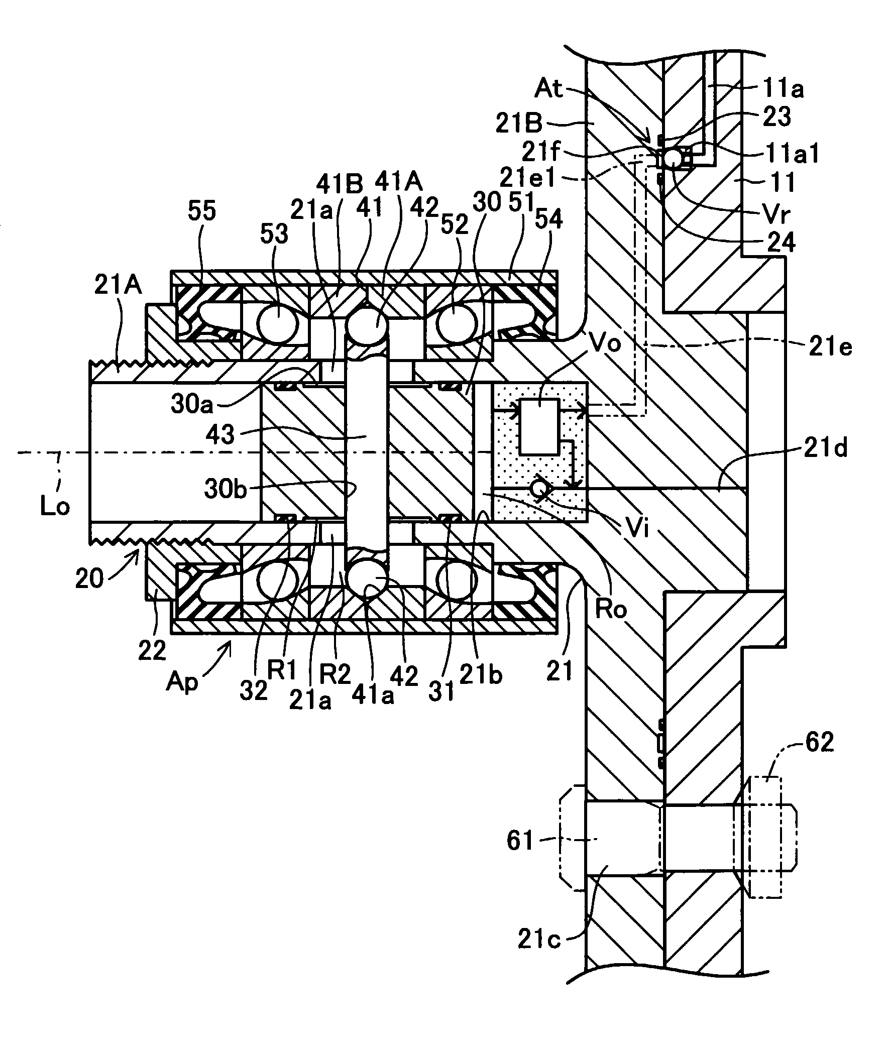
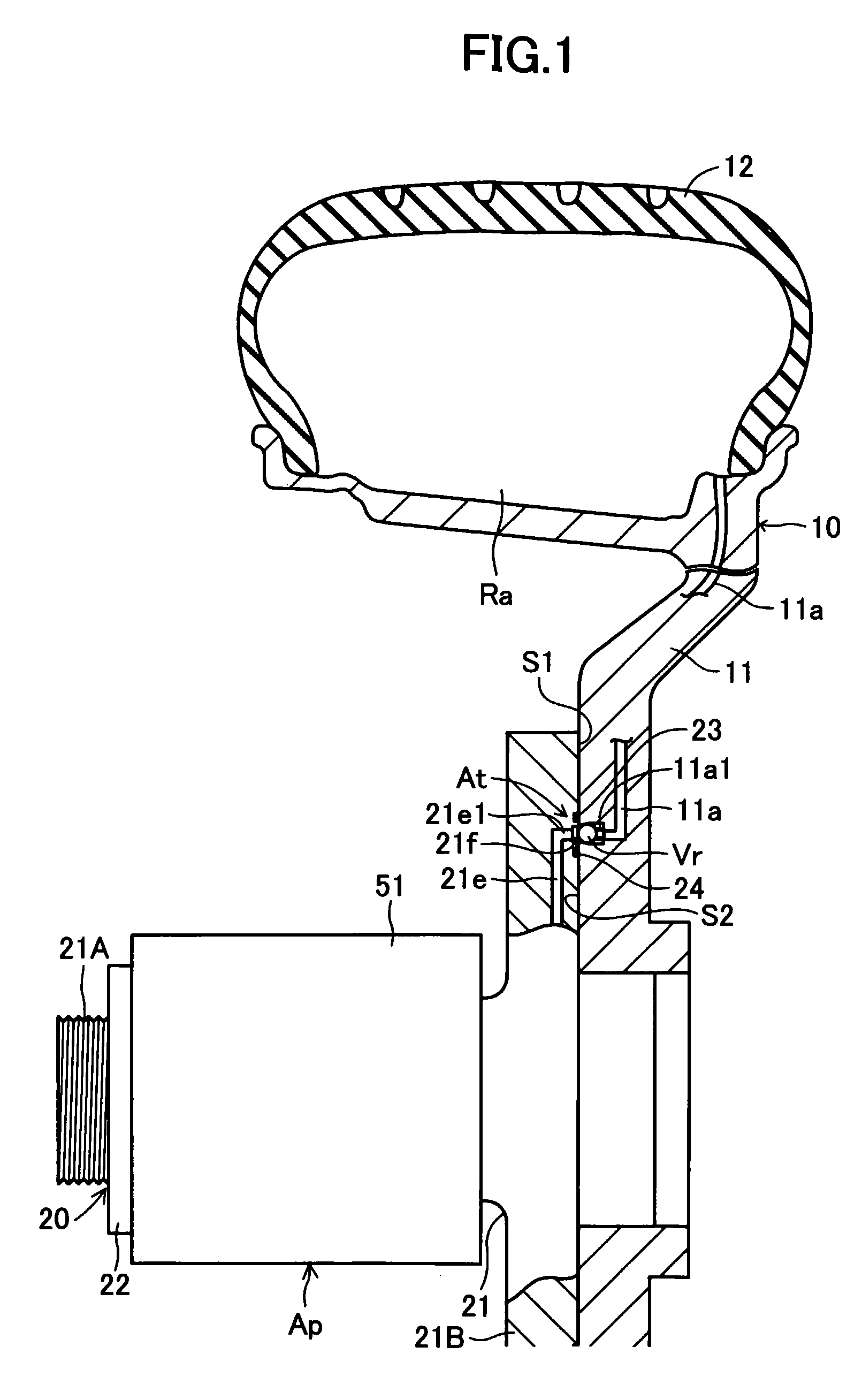
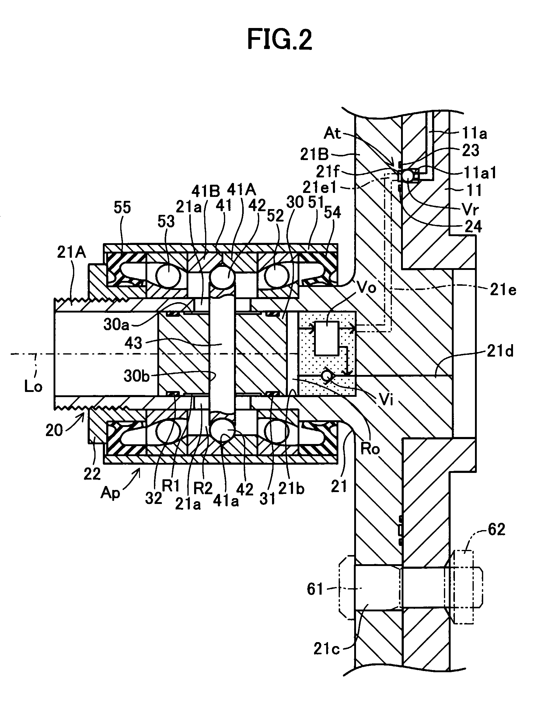
[0014]An embodiment according to the present invention will next be described based on the drawings. FIGS. 1 and 2 schematically show a pressure generating device Ap capable of generating pressurized air with a rotation of an axle hub 20 and an apparatus At for controlling tire inflation pressure (a tire inflation pressure introducing apparatus) which introduces the pressurized air supplied from the pressure generating device Ap into a tire air chamber Ra formed by a wheel 11 and a tire 12 of a vehicle wheel assembly 10. The vehicle wheel assembly 10 is removably mounted onto a disc-shaped flange portion 21B of the axle hub 20 at the wheel 11. It should be noted that the apparatus At for controlling tire inflation pressure is constructed in such a manner that the pressurized air supplied from the pressure generating device Ap is introduced into the tire air chamber Ra of the vehicle wheel assembly 10 through supplying passageways 21e provided in the axle hub 20 and introducing passa...


PUM


Abstract

An apparatus for controlling tire inflation pressure includes an outlet side end portion of a supplying passageway provided in an axle hub that is opened on an outer end surface of a vehicle in a flange portion of the axle hub, and an inlet side end portion of an introducing passageway provided in a wheel that is opened on an inner end surface of the vehicle in the wheel of a vehicle wheel assembly, and by mounting the wheel onto the flange portion, the outlet side end portion and the inlet side end portion are air tightly joined each other. Thus, easiness in mounting the vehicle wheel assembly relative to the flange portion of the axle hub can be improved.

Description

TECHNICAL FIELD[0001]The present invention relates to an apparatus for controlling tire inflation pressure (a tire inflation pressure introducing apparatus), especially, to an apparatus for controlling tire inflation pressure which is constructed in such a manner that pressurized air supplied from a pressure generating device is introduced into a tire air chamber of a vehicle wheel assembly through at least a supplying passageway provided in an axle hub and an introducing passageway provided in a wheel of the vehicle wheel assembly removably mounted onto a flange portion of the axle hub.BACKGROUND ART[0002]An apparatus for controlling tire inflation pressure of this kind is disclosed, for example, in Japanese. Patent Application Laid-Open (kokai) No. Hei 11-139118 (hereinafter referred to as Patent Document 1). In the apparatus for controlling tire inflation pressure described in the Patent Document 1, the pressurized air supplied from the pressure generating device can be introduce...

Claims


Application Information

Patent Timeline
Patent Type & Authority Patents(United States)
IPC IPC(8): B60C23/12
CPCB60C23/12B60C23/003B60C23/00345B60C23/00318B60C23/137B60C23/10B60C23/00
Inventor ISONO, HIROSHI
Owner TOYOTA JIDOSHA KK
Why Eureka
Try Eureka