Connection element and a sheet pile wall having such a connection element

a technology of connection elements and sheet pile walls, which is applied in the direction of thin material processing, artificial islands, construction, etc., can solve the problems of simple interlock configuration, connection elements encountered problems, and limit the production of interlocks for connecting

Active Publication Date: 2011-11-01
SHEET PILE LLC
View PDF3 Cites 8 Cited by
  • Summary
  • Abstract
  • Description
  • Claims
  • Application Information

AI Technical Summary

Benefits of technology

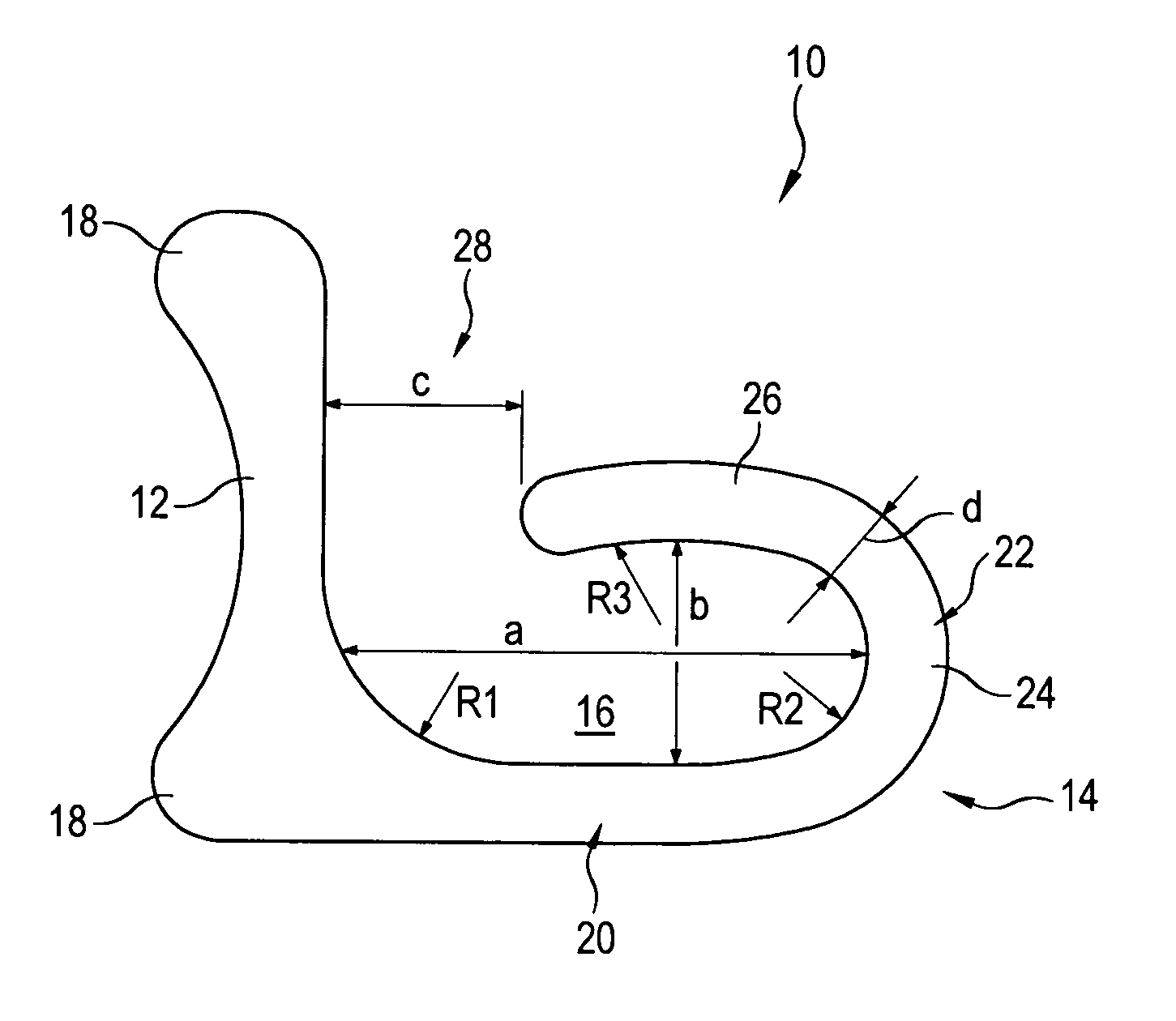
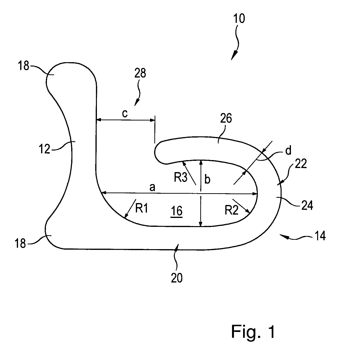
It is furthermore recommended to correlate the greatest width of the jaw, and thus indirectly also the greatest inner width of the inner chamber, with the material thickness of the hook section perpendicular to the longitudinal direction of the hook section. In this manner, by integrating the material thickness of the hook section, a direct correlation between the section modulus of the connection element and the dimensioning of the hook strip is established. It has shown to be particularly advantageous if the ratio between the material thickness of the hook section viewed perpendicular to the longitudinal direction of the hook section and the greatest width of the jaw is in a range from 0.4 to 0.8, preferably at 0.6. Maintaining this ratio on the one hand ensures a sufficient section modulus for the light profiles to be hung while on the other hand retains the desired flexibility when using light profiles of different manufacturers and of different dimensions.
To ensure that the interlock of the light profile that engages in the hook strip does not disengage from the hook strip even in extreme installation positions, it is additionally recommended that the ratio of the greatest inner width of the inner chamber to the greatest width of the inner chamber viewed perpendicular to the longitudinal direction of the connection section is in a range between 2.3 and 2.5 preferably at 2.4. Compared to the state-of-the-art, this achieves a long and at the same time slim dimensioning of the inner chamber of the hook strip that is accompanied by a good support of the interlock and allows also for taking up long dimensioned interlocks.
With this design, it is of particular advantage when the more than 180° arc-shaped contour of the hook strip is achieved, with the first arc-shaped section exhibiting an arc length having a maximum of 165° and the second arc-shaped section an arc length having a maximum of 65°. This achieves that, here also the design of the first arc-shaped section directly influences the design of the second arc-shaped section, creating a protracted arc as the hook section.
To achieve a stress pattern at the transition from the base strip into the connection section of the hook strip that is as uniform as possible, it is recommended in one particularly advantageous embodiment of the connection element according to the invention that the base strip transitions into the connection section at its inside that defines its inner chamber under formation of a radius. It is of particular advantage if the nominal value of the radius corresponds at least approximately to the nominal value of the width of the jaw. Dimensioning the radius and the width of the jaw equally ensures a sufficient freedom to pivot for the interlock of the engaged light profile.
In another particular advantageous embodiment of the connection element according to the invention, it is designed as a weld-on profile, where the rear side of the base strip that points away from the hook strip serves as a weld-on surface for welding to a component of the sheet pile wall, for example for welding to the lateral surface area of a tubular pile, whereby the weld-on surfaces are provided at the longitudinal edges of the base strip, preferably with two additional weld-on elevations that run parallel to each other and extend across the entire length of the connection element, additionally facilitating the welding procedure.
With one particularly advantageous development of this embodiment of the connection element according to the invention, the one free end of the first base strip transitions into the connection section of the first hook strip while the other free end of the first base strip transitions into the second base strip, preferably by forming a radius. The jaw of the second hook faces the flat side of the first base strip that points away from the first hook strip. In this manner, a particularly compact and thus dimensionally stable connection element can be provided.

Problems solved by technology

Due to the manufacturing process, only sheet piles with relatively thin walls can be manufactured, limiting the production of interlocks for connecting the light profiles to each other or even with other components of the sheet pile wall to simple interlock configurations.
However, light profiles are characterized by a multitude of variations, for example in the wall thickness of the light profiles, such that the known connection elements encountered problems when using connection elements for light profiles made by different manufacturers or with different dimensions.

Method used


Image

  • Connection element and a sheet pile wall having such a connection element
  • Connection element and a sheet pile wall having such a connection element
  • Connection element and a sheet pile wall having such a connection element

Examples


Embodiment Construction

FIG. 1 shows a top view of the front face of a first preferred embodiment of a connection element 10 according to the invention. Viewed across its length, the connection element 10 has a uniform cross-section and is designed as a weld-on profile.

The connection element 10 features a base strip 12 with a hook strip 14 protruding at least approximately at a right angle from the longitudinal edge of said base strip as shown at the bottom of FIG. 1 and enclosing together with the base strip 12 an inner chamber 16. Two weld-on elevations 18 are provided at the back side of the base strip 12 that points away from the hook strip 14 and transitions into the respective longitudinal edge of the base strip 12.

The hook strip 14 features a straight connection section 20 that transitions flush into the longitudinal edge of the base strip 12 and that transitions at its end into an arc-shaped hook section 22. The inner side of the base strip 12 that defines the inner chamber 15 transitions into the ...


PUM


Abstract

A connection element for light profiles in a sheet pile wall has a base strip (12) for attaching to a component of the sheet pile wall and a hook strip (14) provided at the flat side of the base strip (12) for engaging the interlock (32) of a light profile (30). The hook strip (14) that encloses an inner chamber (16) exhibits a straight connection section (20) that originates at the base strip (12) and runs at least approximately at a right angle to the longitudinal direction of the base strip (12) and a hook section (22) that follows the connection section (20) and runs in an arc-like manner for at least 180°, with the free end of said hook section (22) together with the flat side of the base strip (12) defining a jaw (28). According to the invention, the ratio between the greatest inner width (a) of the inner chamber (16) of the hook strip (14) to the width (c) of the opening jaw (28) is in a range between 2.6 and 2.9.

Description

BACKGROUND OF THE INVENTIONThe invention relates to a connection element for light profiles intended for use in a sheet pile wall, the connection element having a base strip for attaching to a component of the sheet pile wall and a hook strip provided at the flat side of the base strip for engaging the interlock of a light profile, whereby the hook strip that encloses an inner chamber exhibits a straight connection section that originates at the base strip and runs at least approximately at a right angle to the longitudinal direction of the base strip, and a hook strip that follows the connection section and runs in an arc-like manner for at least 180°, where the end of said hook strip together with the flat side of the base strip define a jaw. The invention also relates to a sheet pile wall made of light profiles and potentially of provided carrier elements, whereby at least two light profiles and / or at least one light profile and one carrier element are connected to each other by ...

Claims


Application Information

Patent Timeline
Patent Type & Authority Patents(United States)
IPC IPC(8): E02D5/00
CPCE02D5/02E02D5/08Y10T428/24017
Inventor HEINDL, RICHARD
Owner SHEET PILE LLC
Why Eureka
Try Eureka