Apparatus for a cam-based jack assembly for use in materials, testing machines and an accompanying method for use therewith

a technology of cam-based jacks and jack assemblies, which is applied in the direction of mechanical measuring arrangements, instruments, and using mechanical means, etc., can solve the problems of reducing the mechanical force applied by the cam alone onto the grip, injecting unwanted artifacts into the resulting amount of deformation, and causing the effect of increasing the force and eliminating the artifacts of mechanical test results

Active Publication Date: 2010-11-09
DYNAMIC SYST INC
View PDF13 Cites 9 Cited by
  • Summary
  • Abstract
  • Description
  • Claims
  • Application Information

AI Technical Summary

Benefits of technology

[0014]The material of the push block is selected to have a sufficient modulus of elasticity that is a compromise value, namely, on the one hand, to sufficiently deflect around and pinch the eccentric at top dead-center positioning of the cam but also, on the other hand, to provide sufficient rigidity to withstand and transmit externally applied deforming forces for each “hit” through the jaw housing to the grip and specimen without the cam appreciably absorbing those forces and deforming as a result.
[0017]As a result of increased force produced by the cam and the deflection of the resilient push block against the eccentric which, in turn, inhibits further rotational movement of the cam, advantageously, the cam will not “back off” its top dead-center position during its subsequent use during a mechanical test program that involves a succession of hits, and thus will securely hold the specimen in a proper fixed position relative to the jaw housing throughout the test program. This, in turn, will substantially, if not totally, eliminate artifacts in mechanical test results which might otherwise arise from unwanted specimen movement during the test program resulting from unwanted loosening of a conventional screw-type jack assembly.

Problems solved by technology

However, cams have traditionally not been used as a component of jack assemblies used in materials testing systems for the simple reason that a cam has a tendency to loosen unless the cam is jacked past its center position, i.e., rotated “over-center”.
If a cam were to be used in a jack assembly to properly hold that one grip in its corresponding jaw, a problem arises in that once the cam were to be rotated over-center to lock its grip in place, a mechanical force applied by that cam alone onto that grip decreases from its peak value that arises at a top dead center position of the cam.
Consequently, once the cam would be turned over-center, that force applied by the cam decreases from its peak value applied at the top dead center position of the cam, thus reducing the lock force holding the grip in position during each subsequent hit, thus potentially allowing some specimen movement which, in turn, might inject some unwanted artifact into the resulting amount of deformation arising from that hit.
Such a result may be problematic.
Unfortunately, a screw that could withstand that much torque would likely be too large to comfortably fit within a jack assembly used in a materials testing system, and hence, in that case, would render a screw-type jack assembly impractical.

Method used


Image

  • Apparatus for a cam-based jack assembly for use in materials, testing machines and an accompanying method for use therewith
  • Apparatus for a cam-based jack assembly for use in materials, testing machines and an accompanying method for use therewith
  • Apparatus for a cam-based jack assembly for use in materials, testing machines and an accompanying method for use therewith

Examples


Embodiment Construction

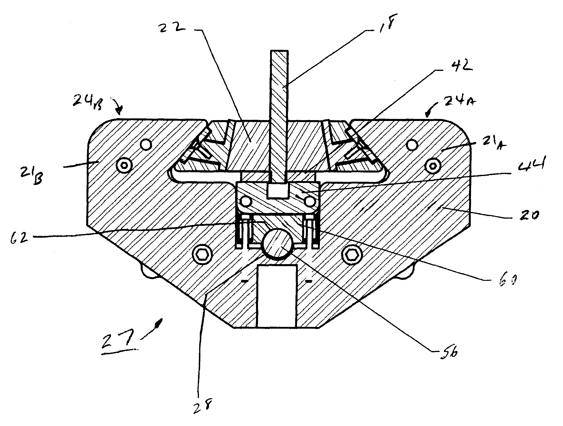
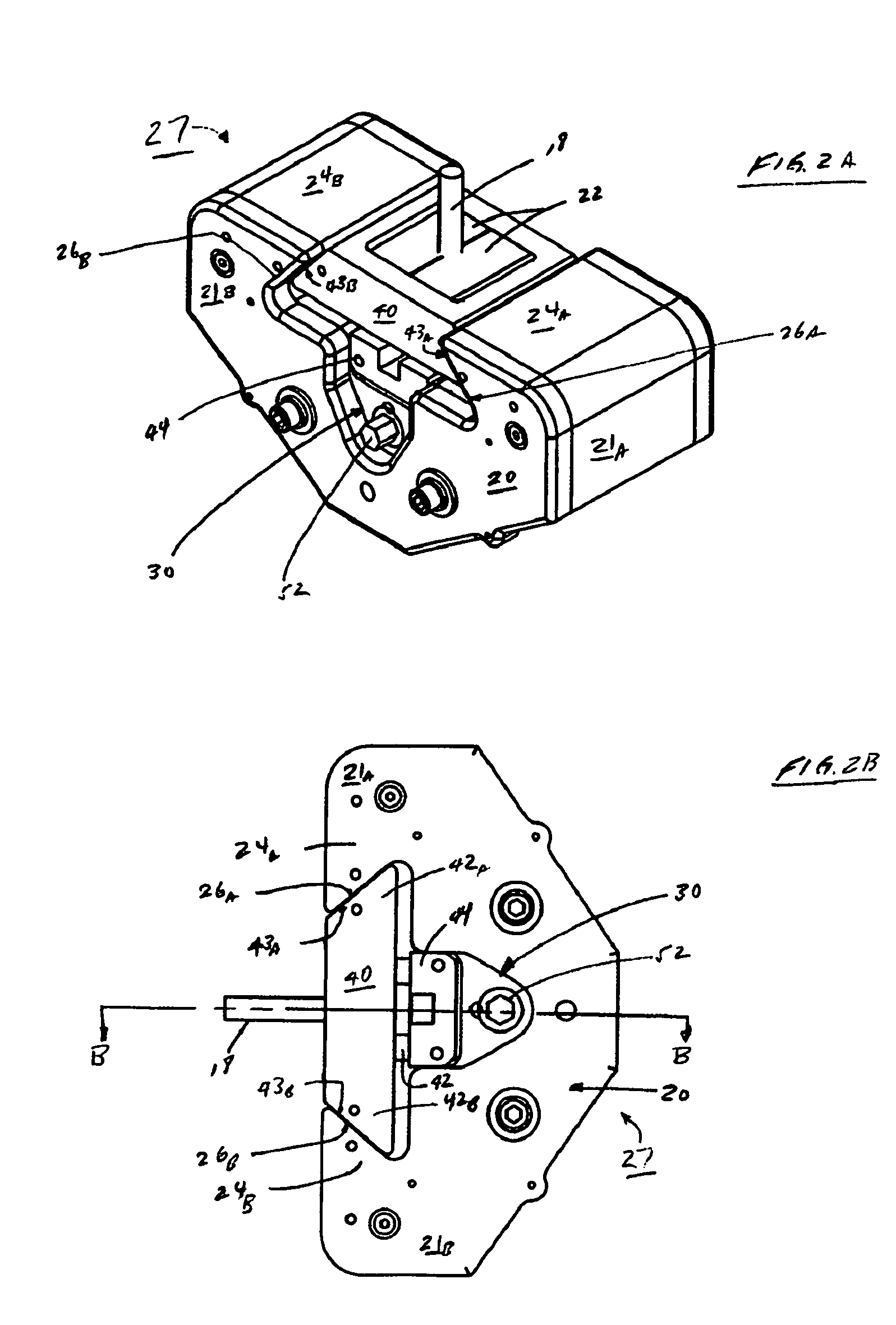
[0037]My inventive jack assembly can be used across a wide variety of applications where a removable piece is to be mechanically locked in place between two opposing inwardly facing projections of a pair of arms extending out of a common housing, where the piece and housing abuttingly mate through complementary wedge or other appropriately shaped surfaces that provide a sufficient frictional coupling to resist relative movement therebetween. To simplify the discussion and facilitate understanding, I will illustratively describe my inventive assembly in the context of use in a mechanical materials test machine and particularly within a jaw in that machine which holds a specimen grip.

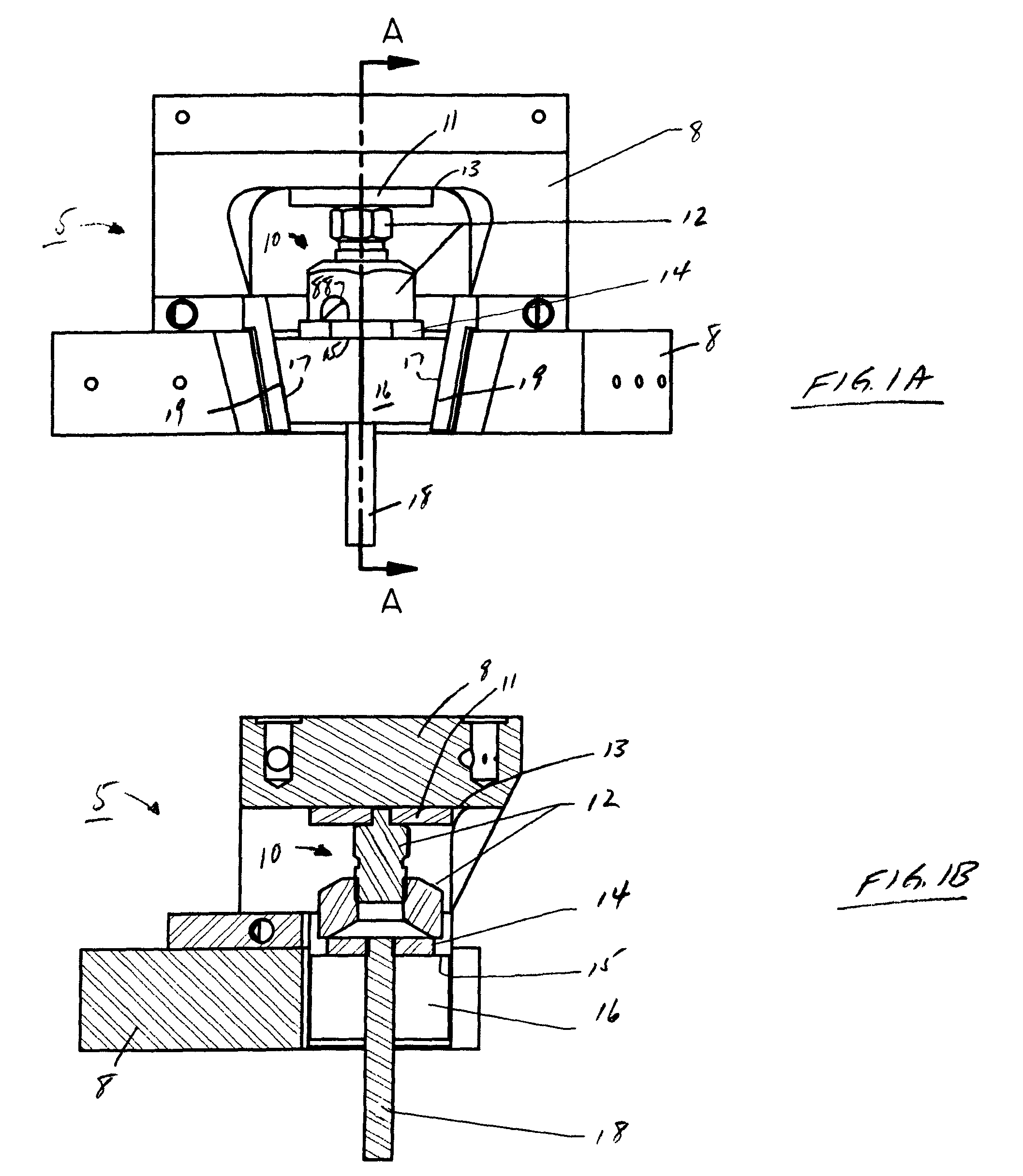
[0038]FIGS. 1A and 1B respectively depict a side view of jaw 5 used in a mechanical testing system and a cross-sectional view taken across lines A-A shown in FIG. 1A of this jaw. Conventionally, as shown in these two figures, specimen grip 16, which securely holds mechanical test specimen 18, is itself po...


PUM


Abstract

A jack assembly, for use in a materials testing system, utilizes both a cam and a resilient push block. The cam, having an progressive eccentric, is situated between the push block and a jaw housing and located partially within a corresponding shallow channel in each such that both channels effectively straddle the cam. The channels accommodate axial rotation of the cam. The push block is formed of a material with an appropriate modulus of elasticity such that bending moments, particularly at ends of the push block and resulting from axial rotation of the eccentric to its top dead-center position, cause the channel in the push block to elastically deform and increasingly and sufficiently deflect against and around the eccentric, thus increasingly pinching the eccentric and securely locking the cam, push block and specimen grip in their proper positions.

Description

CLAIM TO PRIORITY[0001]This application claims priority of my co-pending United States provisional patent application entitled “Cam Jack System for Use in Materials Testing Machines”, filed on Nov. 30, 2007 and assigned Ser. No. 61 / 004,825; and which is incorporated by reference herein.BACKGROUND OF THE DISCLOSURE[0002]1. Field of the Invention[0003]This invention pertains to apparatus and an accompanying method for a jack assembly that secures a grip and specimen held thereby into proper position in a jaw of a materials testing machine and applies suitable pressure and restraint to the grip during mechanical testing. The present invention is well suited for use in a variety of different mechanical and thermo-mechanical material testing machines, including those which provide compressive and tensile testing of a mechanical test specimen.[0004]2. Description of the Prior Art[0005]Conventional materials testing machines utilize a wide range of screw jacks, wedge plates and other types...

Claims


Application Information

Patent Timeline
Patent Type & Authority Patents(United States)
IPC IPC(8): G01B5/30
CPCG01N3/04
Inventor LINDEMAN, NORMAN A.
Owner DYNAMIC SYST INC
Why Eureka
Try Eureka