Rotatable graphic assembly

a graphic assembly and rotating technology, applied in the direction of identification means, electrical apparatus casings/cabinets/drawers, instruments, etc., can solve the problems of changing the orientation of the graphic, such as the maker's logo, on the exterior of the computer, and affecting the use of the computer

Inactive Publication Date: 2011-11-08
HON HAI PRECISION IND CO LTD
View PDF3 Cites 11 Cited by
  • Summary
  • Abstract
  • Description
  • Claims
  • Application Information

AI Technical Summary

Problems solved by technology

As such, a graphic, such as a maker's logo, displayed on the exterior of the computer is also changed to an unfavorable orientation.

Method used


Image

  • Rotatable graphic assembly
  • Rotatable graphic assembly
  • Rotatable graphic assembly

Examples


Embodiment Construction

[0010]Embodiments of the present rotatable graphic assembly will now be described in detail with reference to the drawings.

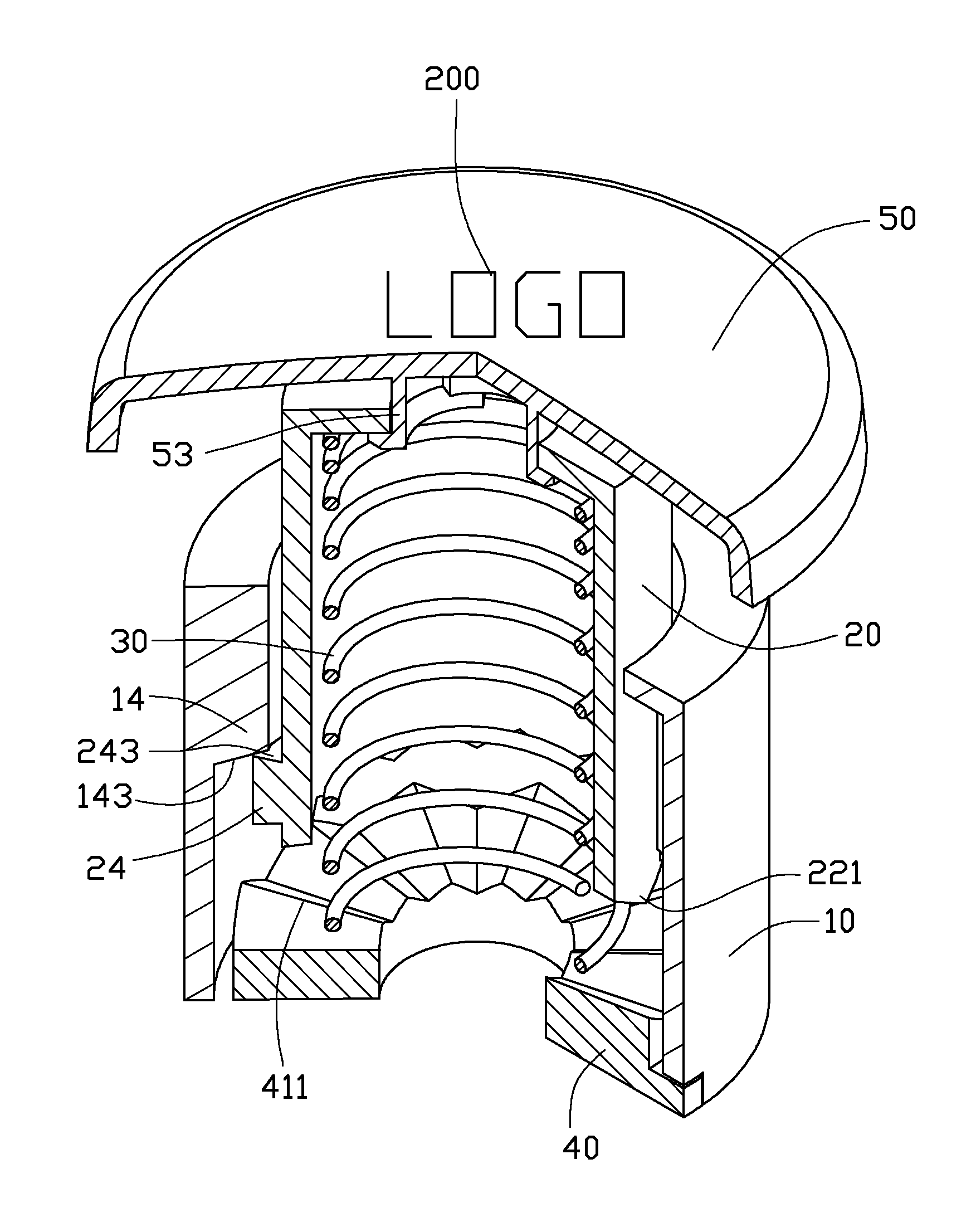
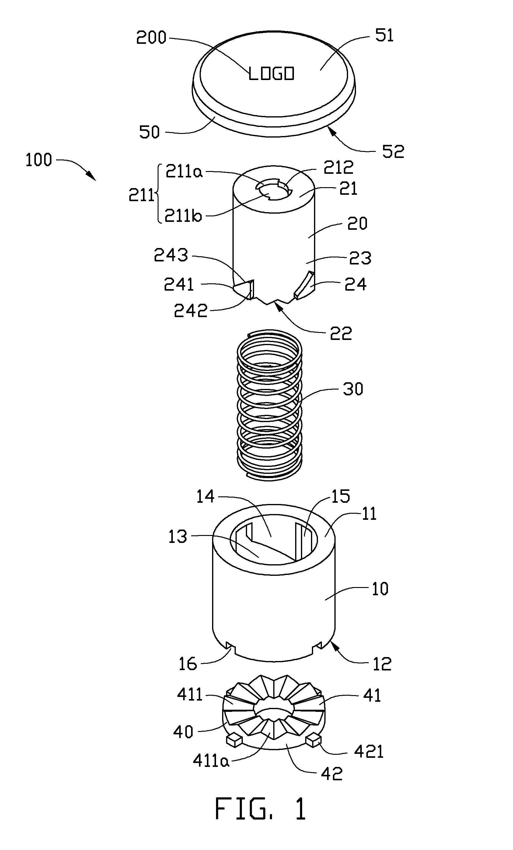
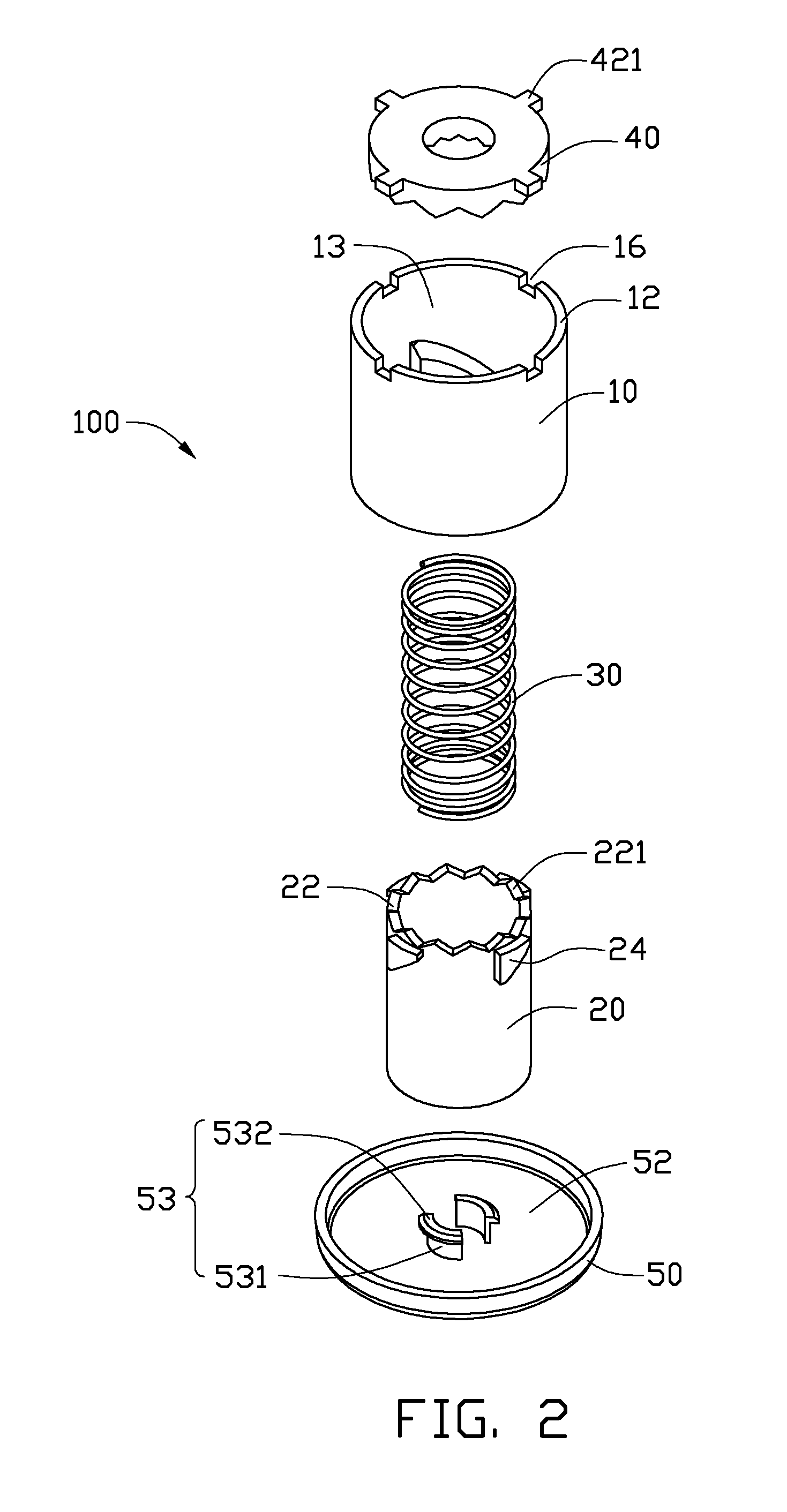
[0011]Referring to FIGS. 1-3, a rotatable graphic assembly 100, according to an exemplary embodiment, includes an outer barrel 10, an inner barrel 20, a spring 30, a base 40, and a button 50.

[0012]The outer barrel 10 includes a first upper surface 11 interconnected by an inner surface 13 to a first lower surface 12. The outer barrel 10 includes four spaced inner teeth 14 uniformly arranged around the circumference of the inner surface 13. The inner teeth 14 are generally bent trapezoids projecting from the first upper surface 11, with each including a first inner side 141, a second inner side 142, and an inner bevel 143. The first inner side 141 and the second inner side 142 are generally parallel to the central axis of the outer barrel 10, and the first inner side 141 is longer than the second inner side 142. The inner bevel 143 interconnects the first inner si...


PUM


Abstract

A rotatable graphic assembly includes an outer barrel including an inner surface and a plurality of inner teeth formed thereon with an inner bevel formed at an end of each inner tooth; an inner barrel received within the outer barrel, the inner barrel including an outer surface and a plurality of outer teeth formed on the outer surface with an outer bevel formed at an end of each outer tooth and movably engaged with the inner teeth, the inner barrel defining a first crown gear portion at one end thereof; a spring sleeved in the inner barrel; a base sealing one end of the outer barrel, and the spring biased between the other end of the outer barrel away from the base and the base; and the base defines a second crown gear facing the first crown gear portion; and a button disposed on the end of the second barrel away from the base and showing a graphic.

Description

BACKGROUND[0001]1. Technical Field[0002]The present disclosure relates to a graphic assembly and, particularly, to a rotatable graphic assembly that can accommodate varying orientations.[0003]2. Description of Related Art[0004]It is not uncommon, in order to save space or for other purposes, to re-orient a desktop computer or a similar device from a vertical configuration to a horizontal configuration. As such, a graphic, such as a maker's logo, displayed on the exterior of the computer is also changed to an unfavorable orientation.[0005]Therefore, a rotatable graphic assembly to overcome the described limitations is desirable.BRIEF DESCRIPTION OF THE DRAWINGS[0006]FIG. 1 is an isometric and exploded view of a rotatable graphic assembly, according to an exemplary embodiment.[0007]FIG. 2 is an isometric and exploded view of the rotatable graphic assembly of FIG. 1, viewed from another angle.[0008]FIG. 3 is a cutaway view of an outer barrel of the rotatable graphic assembly of FIG. 1....

Claims


Application Information

Patent Timeline
Patent Type & Authority Patents(United States)
IPC IPC(8): G09F3/18
CPCG09F3/20G09F7/22Y10T403/599
Inventor CHANG, CHIN-MING
Owner HON HAI PRECISION IND CO LTD
Why Eureka
Try Eureka