Pattern implementation technique

a pattern implementation and pattern technology, applied in the field of computer software systems, can solve the problems of cumbersome and confusing automatic tools for applying patterns in software projects, significant restrictions on the generality and flexibility of patterns that can be implemented, and inability to define patterns in such languages

Inactive Publication Date: 2011-11-08
IBM CORP
View PDF5 Cites 24 Cited by
  • Summary
  • Abstract
  • Description
  • Claims
  • Application Information

AI Technical Summary

Benefits of technology

[0012]Application of the pattern can be initiated by creating an instance of the pattern in a software context associated with a pattern. A graphical representation of the pattern instance can be created in the software context, including a display of the pattern parameters. A user interface can be provided that allows a pattern user to apply arguments to the pattern parameters in the graphical representation of the pattern instance and to modify the software context according to the arguments. The user interface allows a pattern user to iteratively apply the arguments to the pattern parameters and to remove the arguments from the pattern parameters while modifying the software context according to the argument application and removal operations.

Problems solved by technology

Unfortunately, tools that support the creation of patterns using such techniques often introduce significant restrictions on the generality and flexibility of the patterns that can be implemented.
Defining patterns in such languages may be unsupported or difficult.
Automated tools for applying patterns in a software project (sometimes referred to as pattern instantiation) can also be cumbersome and confusing insofar as they tend to be based on batch mode techniques wherein patterns are applied by specifying all of a pattern's parameter arguments or values at one time.
As far as known, current tools do not provide the capability to extend the use of a pattern once it has already been instantiated in the user's code.

Method used


Image

  • Pattern implementation technique
  • Pattern implementation technique
  • Pattern implementation technique

Examples


Embodiment Construction

1. Introduction

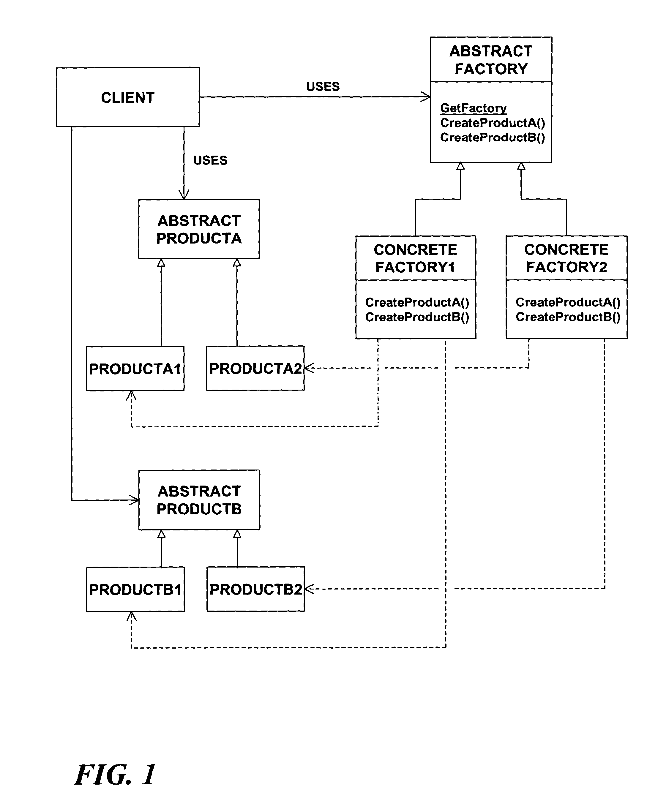
[0038]Turning now to the drawing figures wherein like reference numbers indicate like elements in all of the several views, FIG. 1 illustrates the format of a conventional Abstract Factory pattern in order to facilitate understanding of the present invention based on a specific pattern example. The Abstract factory pattern is a creational pattern that was first identified in the “Design Patterns” work cited by way of background above. In object-oriented software development, a “factory” is a software entity where objects are created. The abstract factory pattern provides a single interface for clients to use in creating families of related objects without having to specify concrete classes.

[0039]In FIG. 1, the objects of interest to the client are based on the abstract class definitions “PRODUCTA” and “PRODUCTB.” Using the analogy of an automobile manufacturing plant, PRODUCTA might be a software representation of an engine while PRODUCTB is a software representation ...


PUM


Abstract

A pattern implementation technique in which a pattern is defined as a software artifact that comprises a pattern signature representing one or more parameters of the pattern and a pattern implementation model representing one or more methods for expanding the pattern in a selected software context by assigning one or more arguments to the one or more parameters. The pattern implementation model can be based on one or more framework code sets, each of which supports the creation of plural patterns by providing a pattern implementation model for a particular software context. The framework code sets can be rendered extensible by a pattern author by virtue of providing methods whose code is adapted to be modified by a pattern author when defining a pattern. The pattern can be applied by creating an instance of the pattern in a software context and presenting a graphical representation of the pattern instance that can be manipulated by the pattern user in order to apply arguments to the pattern parameters.

Description

BACKGROUND OF THE INVENTION[0001]1. Field of the Invention[0002]The present invention relates to computer software systems. More particularly, the invention concerns techniques for defining and applying patterns to or within a software system to cause the system to be structured or behave in a manner dictated by or consistent with the patterns.[0003]2. Description of the Prior Art[0004]In the field of design, a pattern represents an abstract solution that can be brought to bear on a recurring design problem. In formal terms, a pattern can be said to represent a common solution to a common problem in a given context. In the context of software development, patterns are used extensively to solve small and large-scale problems in the design, modeling, implementation, deployment, and maintenance of software systems. The application of a pattern to or within a software system causes the system to be structured and to behave in certain ways dictated by or consistent with the pattern. The ...

Claims


Application Information

Patent Timeline
Patent Type & Authority Patents(United States)
IPC IPC(8): G06F9/44
CPCG06F8/20
Inventor STEVENSON, DAVID R.ABBOTT, JAMES R.FISCHER, JEFFREY M.SCHNEIDER, SCOTT E.ROBERTS, BRIAN K.ANDREWS, MARTHA C.RUEST, DAVID J.GARDNER, SHAWN K.MAGUIRE, CHRISTOPHER D.FUNK, ERIC O.
Owner IBM CORP
Why Eureka
Try Eureka