Refrigerant charge control in a heat pump system with water heater

a heat pump and water heater technology, applied in the field of heat pump systems, can solve the problems of not including any device for controlling the refrigerant charge, system not being optimally efficient in all modes of operation, and heat pumps often have non-utilized heating capacity, etc., to achieve the effect of improving the control of the refrigerant charg

a heat pump and water heater technology, applied in the field of heat pump systems, can solve the problems of not including any device for controlling the refrigerant charge, system not being optimally efficient in all modes of operation, and heat pumps often have non-utilized heating capacity, etc., to achieve the effect of improving the control of the refrigerant charg

US8056348B2Inactive Publication Date: 2011-11-15CARRIER CORP

Image

  • Refrigerant charge control in a heat pump system with water heater
  • Refrigerant charge control in a heat pump system with water heater
  • Refrigerant charge control in a heat pump system with water heater

Examples


Embodiment Construction

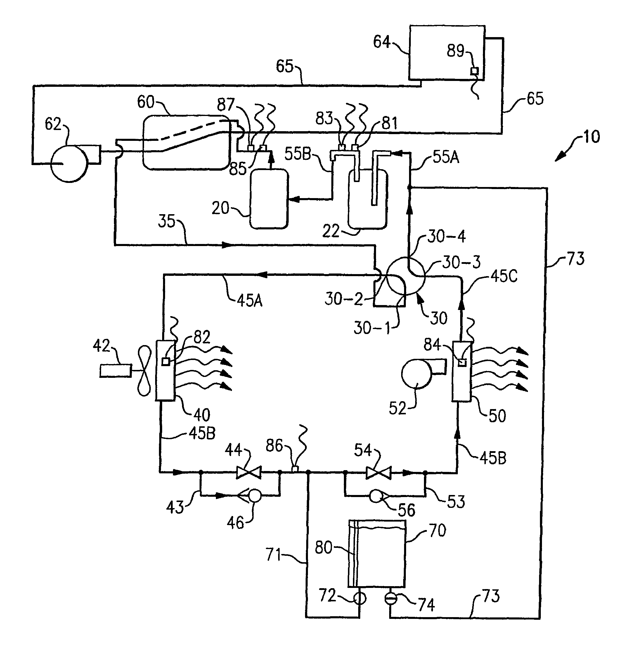
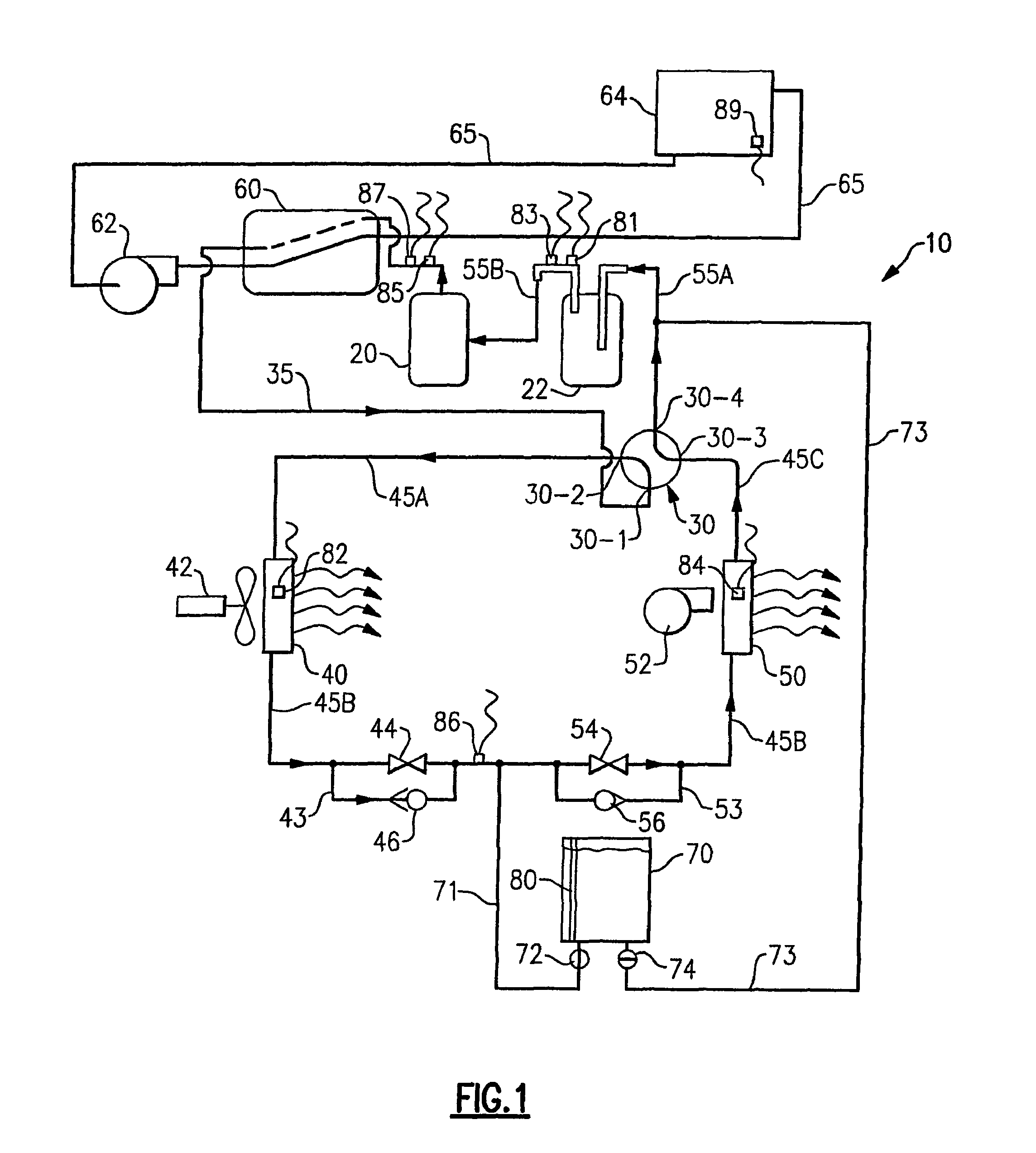
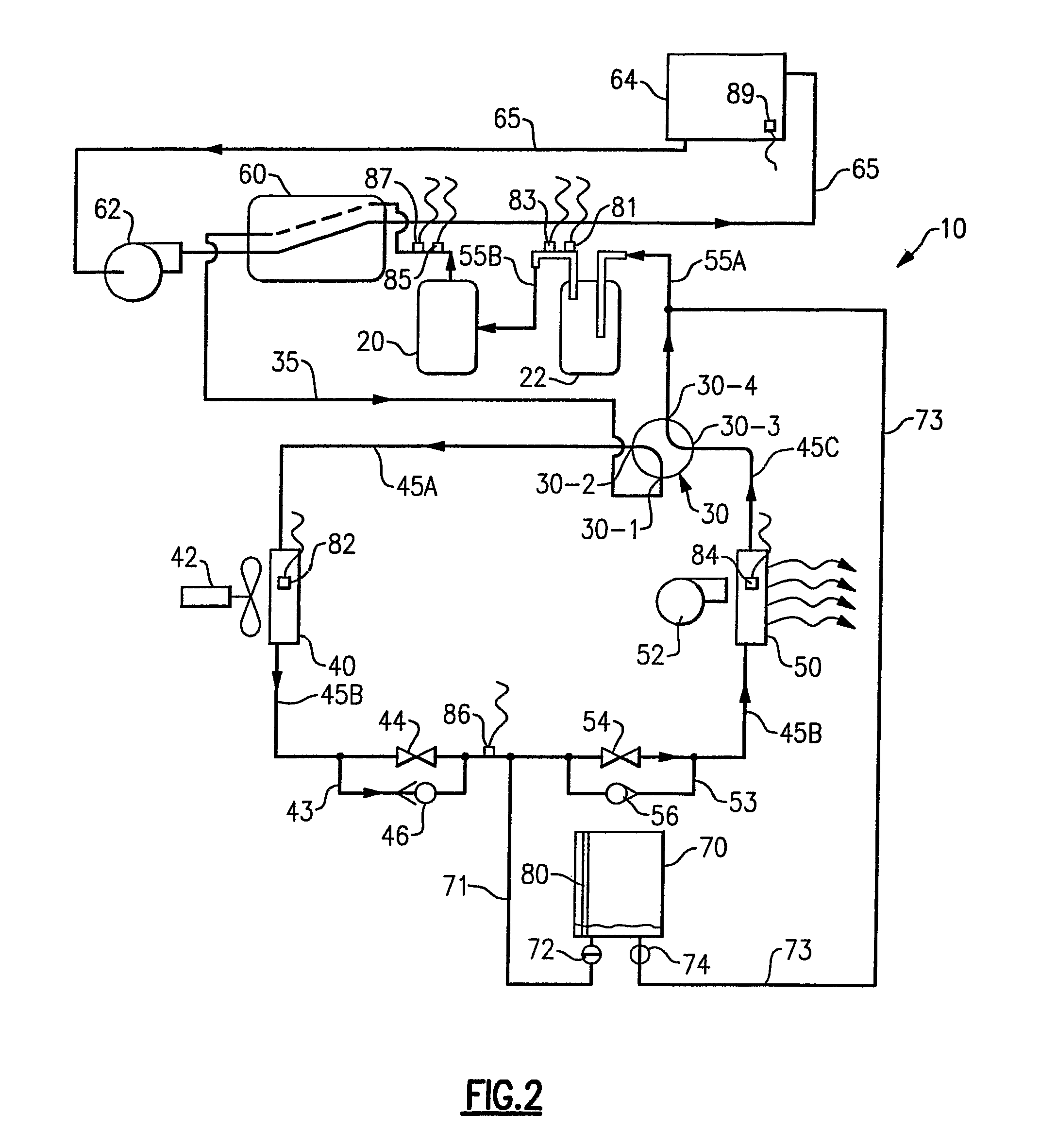
[0026]The refrigerant heat pump system 10, depicted in a first embodiment in FIGS. 1-5 and a second embodiment in FIGS. 6-8, provides not only either heating or cooling to a comfort region, for example an indoor zone located on the inside of a building (not shown), but also auxiliary water heating. The system includes a compressor 20, a suction accumulator 22, a reversing valve 30, an outdoor heat exchanger 40 and associated fan 42 located on the outside of the building in heat transfer relation with the surrounding ambient, an indoor heat exchanger 50 and associated fan 52 situated in the comfort zone, a first expansion valve 44 operatively associated with the outdoor heat exchanger 40 and a second expansion valve 54 operatively associated with the indoor heat exchanger 50. A refrigerant circuit including refrigerant lines 35, 45 and 55 provide a closed loop refrigerant flow path coupling these components in a conventional manner for a heat pump system employing the well known Carn...


PUM


Abstract

A heat pump system includes a compressor, a reversing valve, an outdoor heat exchanger and an indoor heat exchanger in a circuit, and a refrigerant-to-water heat exchanger. In the air cooling with water heating mode, the air heating with water heating mode and the water heating only mode, water from a water reservoir is passed through refrigerant-to-water heat exchanger. A refrigerant reservoir may be provided for use in refrigerant charge control. A refrigerant line (71) couples reservoir to the refrigerant circuit intermediate the outdoor and indoor heat exchangers for directing liquid refrigerant into the reservoir and a refrigerant line (73) couples the refrigerant circuit upstream of the suction inlet to the compressor for returning refrigerant to the refrigerant circuit. A controller controls flow into and from the refrigerant reservoir through selective opening and closing of control valve (72) in line (71) and control valve (74) in line (73).

Description

TECHNICAL FIELD[0001]This invention relates generally to heat pump systems and, more particularly, to heat pump systems including auxiliary liquid heating, including for example heating water for swimming pools, household water systems and the like.BACKGROUND ART[0002]Reversible heat pumps are well known in the art and commonly used for cooling and heating a climate controlled comfort zone with a residence or a building. A conventional heat pump includes a compressor, a suction accumulator, a reversing valve, an outdoor heat exchanger with an associated fan, an indoor heat exchanger with an associated fan, an expansion valve operatively associated with the outdoor heat exchanger and a second expansion valve operatively associated with the indoor heat exchanger. The aforementioned components are typically arranged in a closed refrigerant circuit pump system employing the well known Carnot vapor compression cycle. When operating in the cooling mode, excess heat absorbed by the refrige...

Claims


Application Information

Patent Timeline
15 Nov 2011
Publication
US8056348B2
IPC
F25B45/00
CPC
F25B13/00; F25B45/00; F25B40/04; F25B2313/004; F25B2313/0314; F25B2313/0315; F25B2700/1931; F25B2700/1933
Inventors
MURAKAMI, TOSHIO; TESCHE, CARLOS A.