Rekeyable lock cylinder and rekeying method thereof

a lock cylinder and rekeying technology, applied in the field of lock cylinders, can solve the problems of high lock replacement cost and inconvenience in use, and achieve the effect of reducing rekeying cost and increasing convenience in us

Active Publication Date: 2011-11-15
TAIWAN FU HSING INDAL
View PDF6 Cites 15 Cited by
  • Summary
  • Abstract
  • Description
  • Claims
  • Application Information

AI Technical Summary

Benefits of technology

[0003]The primary object of the present invention is to provide a rekeyable lock cylinder and rekeying method thereof. First, a first matched key is inserted into a plug and then turned to drive the plug and an adjusting block rotating. Next, a pulling force is added to the first matched key for driving the plug and the adjusting block to move and making a position pin to limit the adjusting block. Next, a thrust is added to the first matched key to make a plurality of first rack components be caught by the adjusting block and disengage with a plurality of second rack components. Next, the first matched key is turned to make the position pin position the adjusting block within a cylinder body and then pulled out before inserting a second matched key into the plug. Next, the second matched key is turned to make the adjusting block release from limitation of the position pin and drive the first rack components to reengage with the second rack components. Finally, the second matched key is pulled out to complete the entire rekeying process. Therefore according to the present invention, lock replacement can be completed as soon as rekeying another matched key only without replacing lock cylinder, which may provide advantages of widely reducing rekeying cost and increasing convenience in use.

Problems solved by technology

Lock cylinder of known lock device typically is matched with a proper key so lock cylinder as well as key must be replaced in pair while replacing a lock, which results in high lock-replacing cost and inconvenience in use.

Method used


Image

  • Rekeyable lock cylinder and rekeying method thereof
  • Rekeyable lock cylinder and rekeying method thereof
  • Rekeyable lock cylinder and rekeying method thereof

Examples


Embodiment Construction

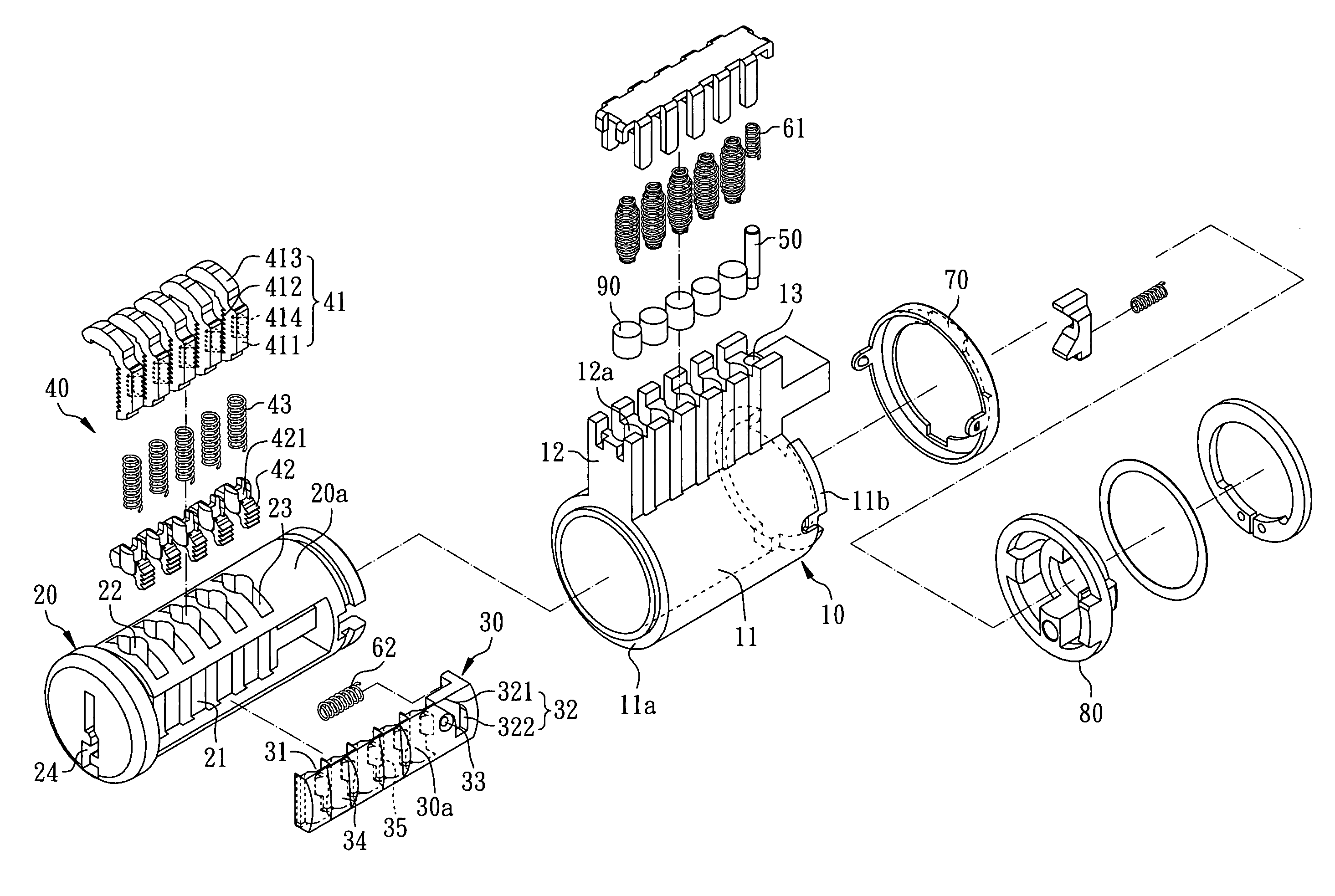
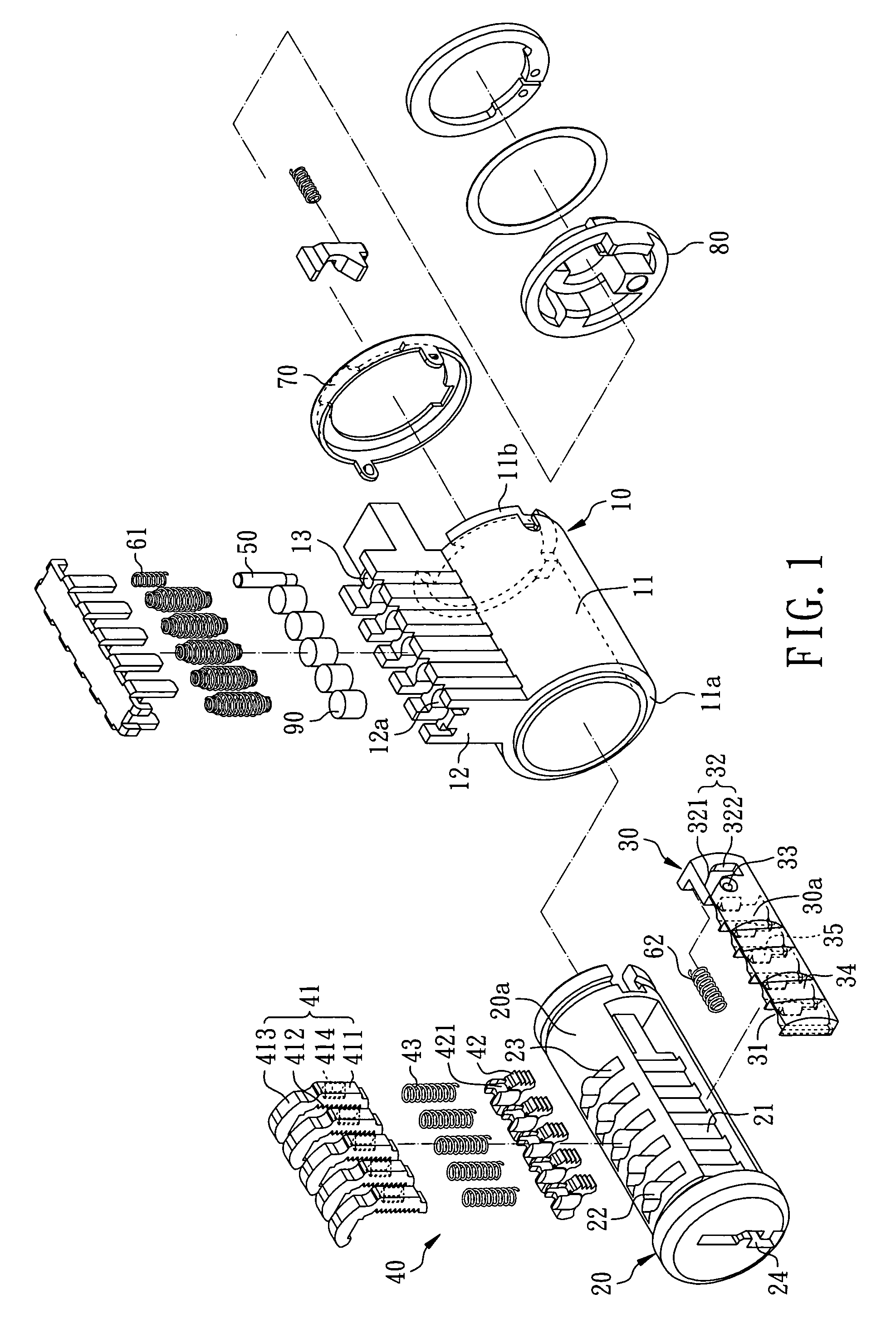
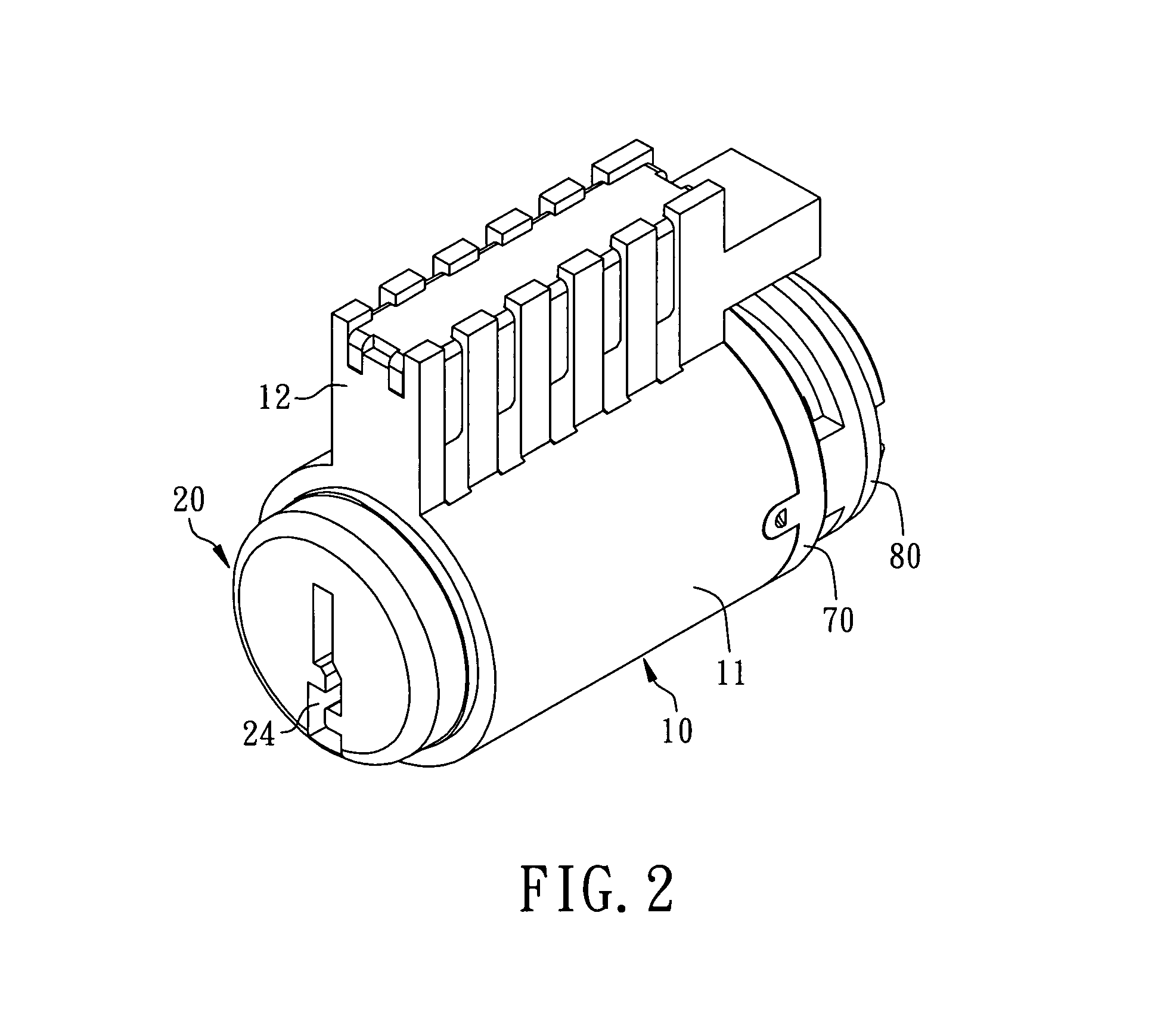
[0031]FIGS. 1 and 2 illustrates a rekeyable lock cylinder in accordance with a preferred embodiment of the present invention, which comprises a cylinder body 10, a plug 20, an adjusting block 30 and a plurality of rack component assemblies 40. The cylinder body 10 has a hollow cylinder portion 11, an extending protrusion 12 formed at one side of the hollow cylinder portion 11 and a through hole 13 formed at the extending protrusion 12. The hollow cylinder portion 11 has a first ending portion 11a and a second ending portion 11b relative to the first ending portion 11a, the extending protrusion 12 has a plurality of upper pin holes 12a for receiving a plurality of upper pins 90, and the through hole 13 communicates with the hollow cylinder portion 11 and is adjacent to the second ending portion 11b of the hollow cylinder portion 11. With reference to FIGS. 1, 3 and 4, the rekeyable lock cylinder further comprises a position pin 50, a first spring 61 for pushing the position pin 50 an...


PUM


Abstract

A rekeyable lock cylinder comprises a cylinder body, a plug, an adjusting block and a plurality of rack component assemblies. The plug disposed within the cylinder body has a trench and a plurality of rack component runners communicating with the trench. The adjusting block disposed at the trench has an arc sidewall, a plurality of leading slots corresponding to the rack component runners one by one and a position groove recessed from the arc sidewall. The position groove has a notch portion and a groove inner portion, wherein a depth of the groove inner portion is larger than a depth of the notch portion. Each of the rack component assemblies comprises a first rack component disposed at the rack component runner and a second rack component capable of engaging with the first rack component. Each of the first rack components has a rib portion located at the leading slot.

Description

FIELD OF THE INVENTION[0001]The present invention is generally relating to a lock cylinder, more particularly to a rekeyable lock cylinder and rekeying method thereof.BACKGROUND OF THE INVENTION[0002]Lock cylinder of known lock device typically is matched with a proper key so lock cylinder as well as key must be replaced in pair while replacing a lock, which results in high lock-replacing cost and inconvenience in use.SUMMARY[0003]The primary object of the present invention is to provide a rekeyable lock cylinder and rekeying method thereof. First, a first matched key is inserted into a plug and then turned to drive the plug and an adjusting block rotating. Next, a pulling force is added to the first matched key for driving the plug and the adjusting block to move and making a position pin to limit the adjusting block. Next, a thrust is added to the first matched key to make a plurality of first rack components be caught by the adjusting block and disengage with a plurality of secon...

Claims


Application Information

Patent Timeline
Patent Type & Authority Patents(United States)
IPC IPC(8): E05B27/04
CPCE05B29/004E05B31/00Y10T70/7452Y10T70/7463Y10T70/7588Y10T70/7599Y10T70/7605Y10T70/7616Y10T70/7734Y10T70/774
Inventor HUANG, CHAO-MINGCHEN, CHI-MING
Owner TAIWAN FU HSING INDAL
Why Eureka
Try Eureka