Calcaneal plate

a technology of calcaneal plate and calcaneal plate, which is applied in the field of orthopedic implants, can solve the problems of affecting the healing effect of the joint, and being totally unsuitable for fracture reconstruction or reduction

Active Publication Date: 2011-11-15
ORTHOHELIX SURGICAL DESIGNS
View PDF11 Cites 52 Cited by
  • Summary
  • Abstract
  • Description
  • Claims
  • Application Information

AI Technical Summary

Problems solved by technology

This joint is vulnerable to substantial damage in particular in falls, or in automobile or vehicle crashes.
However, the prior art plates often had elements that extended beyond the bone to irritate soft tissue such as in particular the peroneal ligaments, which often causes irritation if not eruption of the ligament.
Further, while the idea of loading a flexible planar plate maybe suitable to allow contouring fixed to healthy bone, it is totally unsuitable for reconstruction or reduction of fractures so as to rebuild a fractured bone.

Method used


Image

  • Calcaneal plate
  • Calcaneal plate
  • Calcaneal plate

Examples


Embodiment Construction

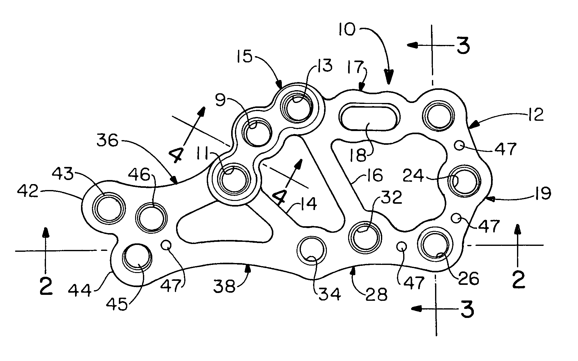
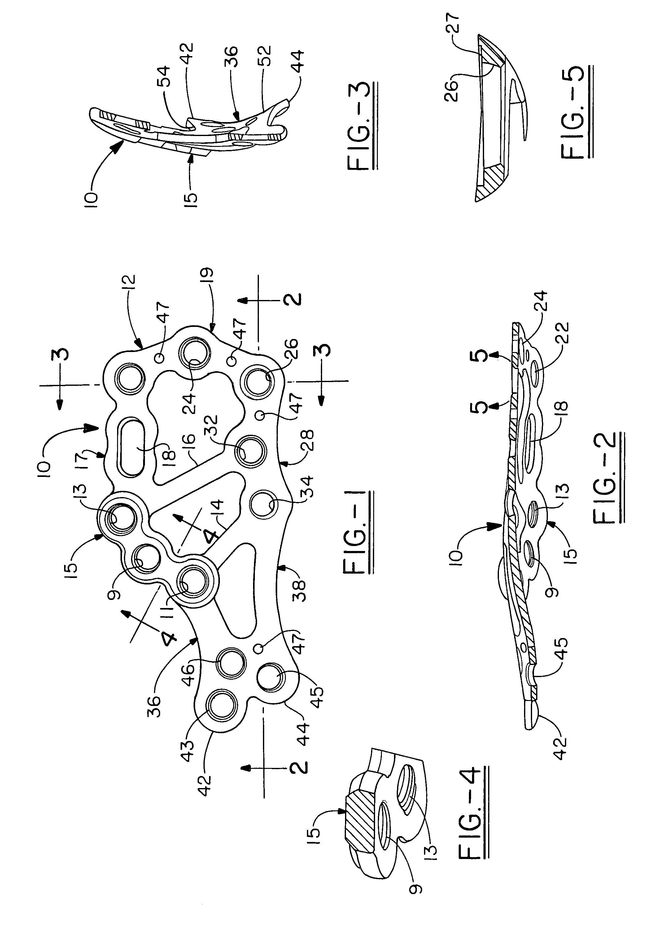
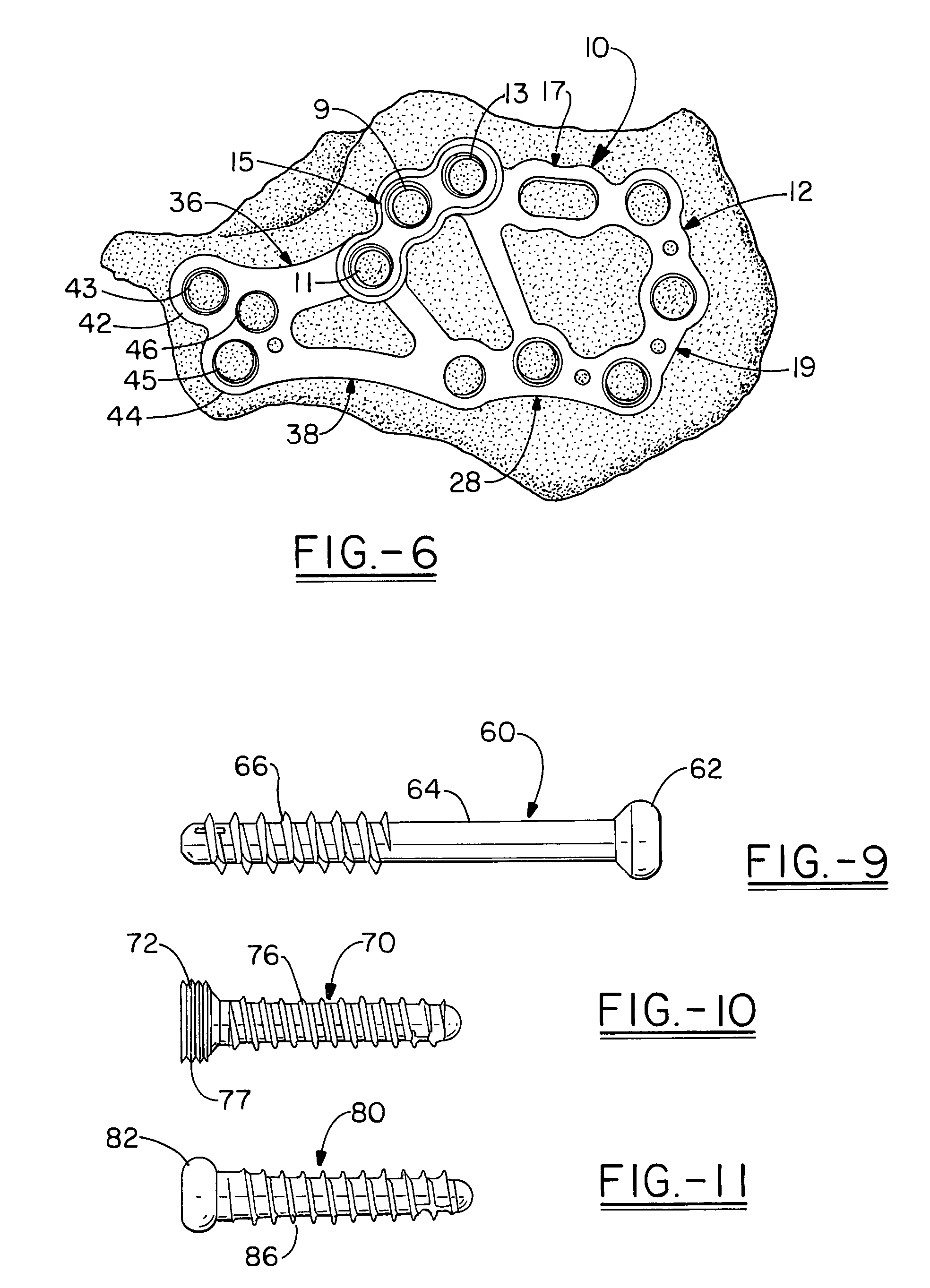
[0022]The calcaneal plate of the present invention is shown from the top in FIG. 1 at 10 and has a top outline comprising a blunt ovoid body 12 which comprises a complete ring (i.e. joined through 180°) of segments beginning at an anterior strut 14 and curving through a reinforced three hole segment (i.e., the posterior facet segment) 15 designed to fit just inferior to the posterior facet and which is reinforced by providing a greater thickness around the screw holes as well as for the areas linking the screw holes to accommodate weight transfer from the tibia to the talus to the calcaneus. The most anterior 11 and the least anterior 13 of the holes in the posterior facet segment 15 preferably are both internally threaded and receive locking screws which have corresponding mating threads on the screw head so as to lock the plate to the bone segments in this area at a pre-selected angle. The angles of the locking threads are selected to provide scaffolding for the sub-chondral suppo...


PUM


Abstract

The present invention is a fully contoured calcaneal plate having substantially no planar surfaces except at the origin. The contoured plate includes radiused sections, one extending inferior to superior is curved inferior to superior in a shape which is close to cylindrical and which approximates the shape of the cuboid bone. The second radiused section is curved in the vicinity of the anterior strut, and in particular at the inferior portion of the plate, to accommodate the peroneal tubercle. The plate has a rectangular or modified ovoid body section and a dog boned shaped tail with triangular placed holes for fixation.

Description

[0001]This Patent application claims priority to U.S. Provisional applications Nos. 60 / 831,647, filed Jul. 18, 2006 for CALCANEAL PLATE and 60 / 880,910, filed Jan. 17, 2007 for CALCANEAL PLATE which is hereby fully incorporated by referenceTHE FIELD OF THE INVENTION[0002]The present invention relates to an orthopedic implant for use in fixation of a calcaneus, including for example, stabilization of a fracture or reconstruction of a deformity.BACKGROUND OF THE INVENTION[0003]The hindfoot joint comprises the junctions formed between the cuboid, calcaneus, and the talus. Mobility in these joints is critical to almost all bipedal movement, and even standing. This joint is vulnerable to substantial damage in particular in falls, or in automobile or vehicle crashes.[0004]The present invention is designed in a first aspect for the most common fracture to the hindfoot joint: i.e. calcaneal fractures of which the most common is a Sander's type II fracture. This type of fracture generally com...

Claims


Application Information

Patent Timeline
Patent Type & Authority Patents(United States)
IPC IPC(8): A61B17/80
CPCA61B17/8061A61B17/8057
Inventor DUCHARME, DUSTINHARTOG, BRYAN D. DENMCGLAMRY, MICHAEL C.DESAI, BHARAT M.KAY, DAVID B.STRNAD, LEE A.
Owner ORTHOHELIX SURGICAL DESIGNS
Why Eureka
Try Eureka