Main circuit of electric power generating apparatus for dispersed power supply

a power supply and power supply technology, applied in the direction of electric generator control, synchronous generators with multiple outputs, instruments, etc., can solve the problems of large impact on winding having the larger number of turns, and achieve the effect of reducing the price of permanent magnet type electric power generator 3 and reducing the amount of expensiv

Inactive Publication Date: 2011-11-15
TOYO DENKI SEIZO KK
View PDF15 Cites 2 Cited by
  • Summary
  • Abstract
  • Description
  • Claims
  • Application Information

AI Technical Summary

Benefits of technology

[0029]The invention can provide a main circuit of an electric power generating apparatus for dispersed power supply, which enables the price of the permanent magnet type electric power generator 3 to be reduced by decreasing amounts of expensive permanent magnets in the permanent magnet type electric power generator 3 and enables a maximum output curve Pt and an approximate output curve Ps to substantially coincide with each other.

Problems solved by technology

Particularly, the second winding having the larger number of turns will be greatly affected by the influence of flux reducing effect which is in proportion to the product of lagging current and the number of turns of the winding owing to the large number of turns although the current flowing through the second winding is small, while the first winding cannot output a large alternating current because of its small number of turns.

Method used


Image

  • Main circuit of electric power generating apparatus for dispersed power supply
  • Main circuit of electric power generating apparatus for dispersed power supply
  • Main circuit of electric power generating apparatus for dispersed power supply

Examples


embodiment 1

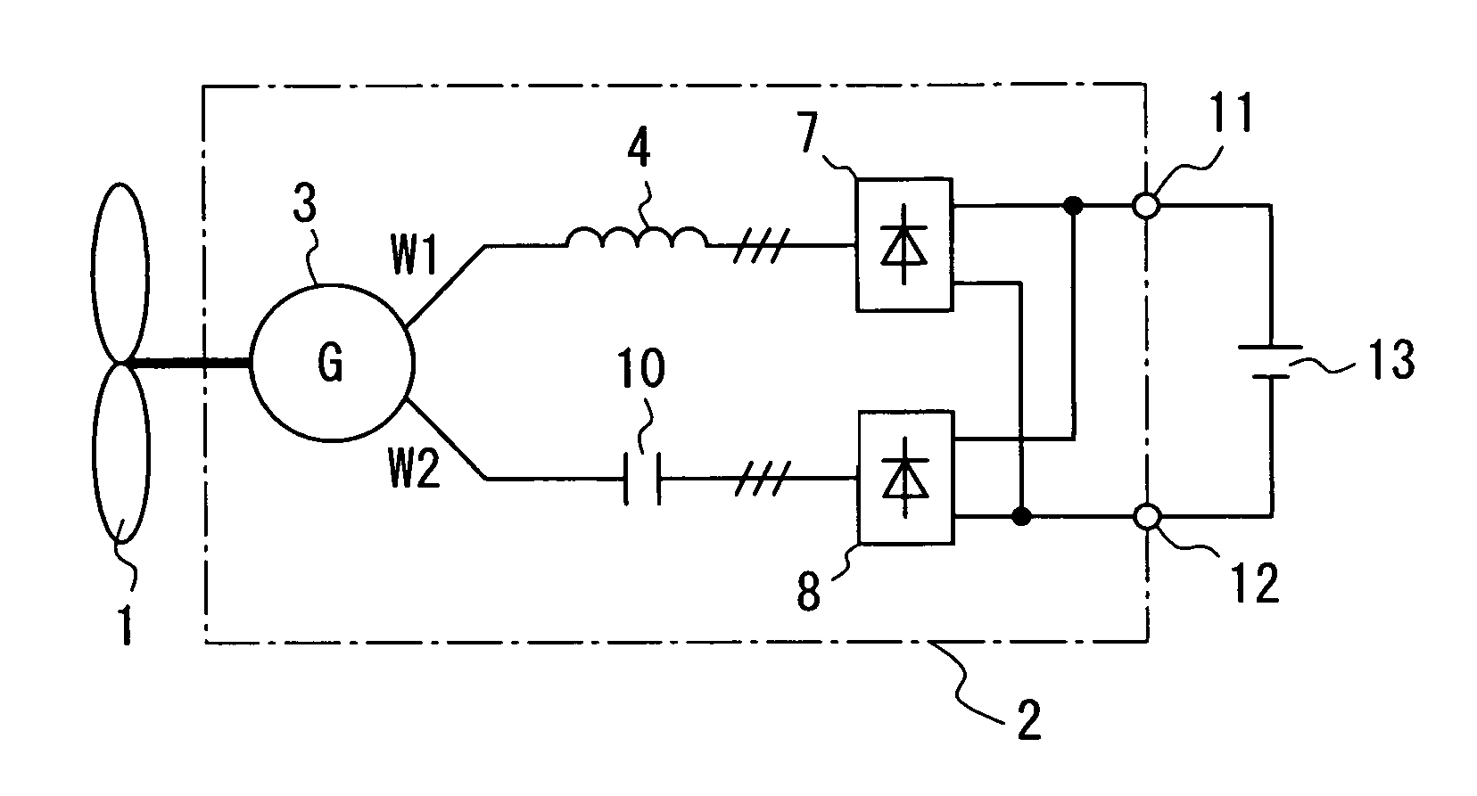
[0053]FIG. 1 is a view for explaining the main circuit of the electric power generating apparatus for dispersed power supply driven by a windmill or waterwheel to obtain direct current output according to the invention.

[0054]In FIG. 1, reference numeral 10 denotes a capacitor, and the same components as those in FIG. 13 are identified by the same reference numerals as those used in FIG. 13. The main circuit of the electric power generating apparatus according to the invention will be explained hereinafter with reference to FIG. 1 and further FIGS. 5 and 6 explaining the principle of the invention.

[0055]A capacitor 10 and further a second rectifier 8 are connected in series to the alternating current output terminal W2 of a second winding having a larger number of turns. A first reactor 4 and further a first rectifier 7 are connected in series to the alternating current output terminal W1 of a first winding having a smaller number of turns.

[0056]The outputs of the first and second re...

embodiment 2

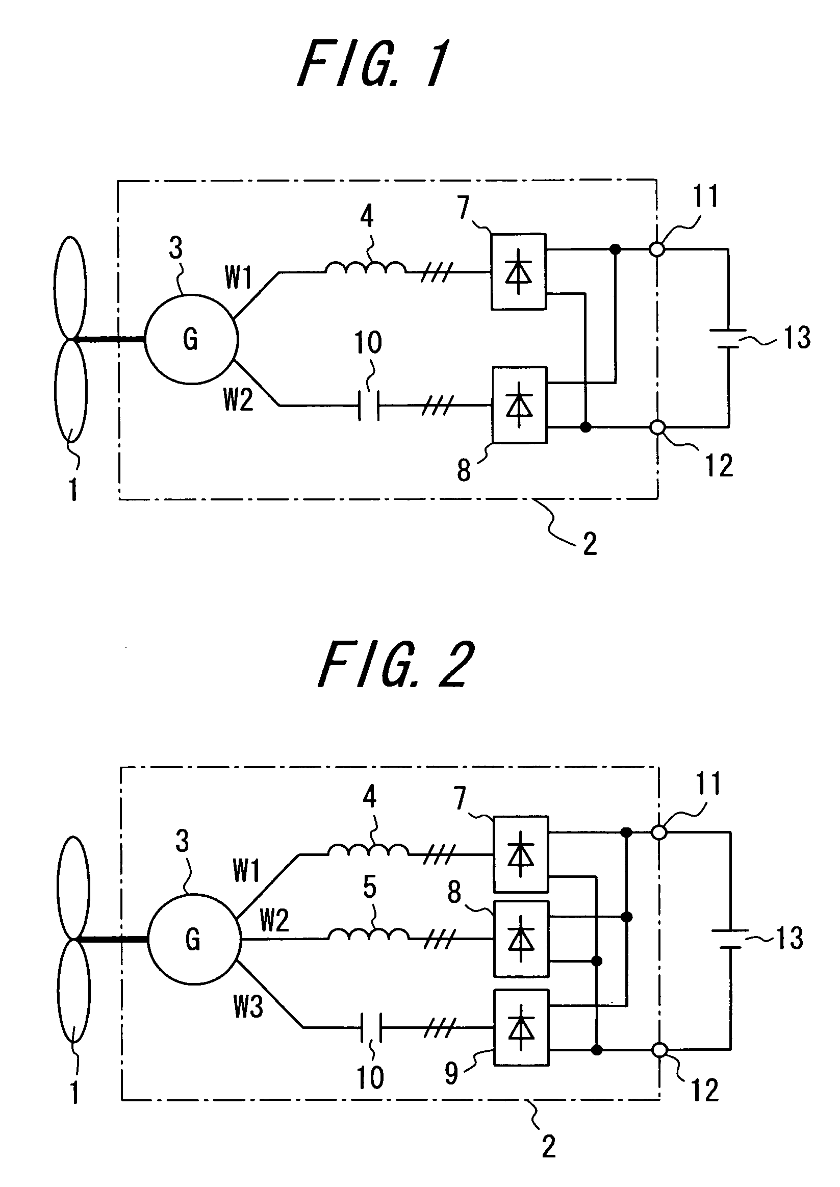
[0068]FIG. 2 illustrates the second embodiment of the invention.

[0069]FIG. 2 is a view illustrating the main circuit of an electric power generating apparatus for dispersed power supply including a permanent magnet type electric power generator 3 having three kinds of windings among which one kind winding has the largest number of turns to which the present invention is applied.

[0070]In FIG. 2, reference numeral 9 denotes a third rectifier, and the same components as those in FIGS. 1 and 13 are identified by identical reference numerals.

[0071]The second embodiment of the invention will be described with reference to FIG. 2 hereinafter.

[0072]A capacitor 10 and further a third rectifier 9 are connected in series to the alternating current output terminal W3 of the third winding having the largest number of turns in the permanent magnet type electric power generator 3. A second reactor 5 and further a second rectifier 8 are connected in series to the alternating current output terminal...

embodiment 3

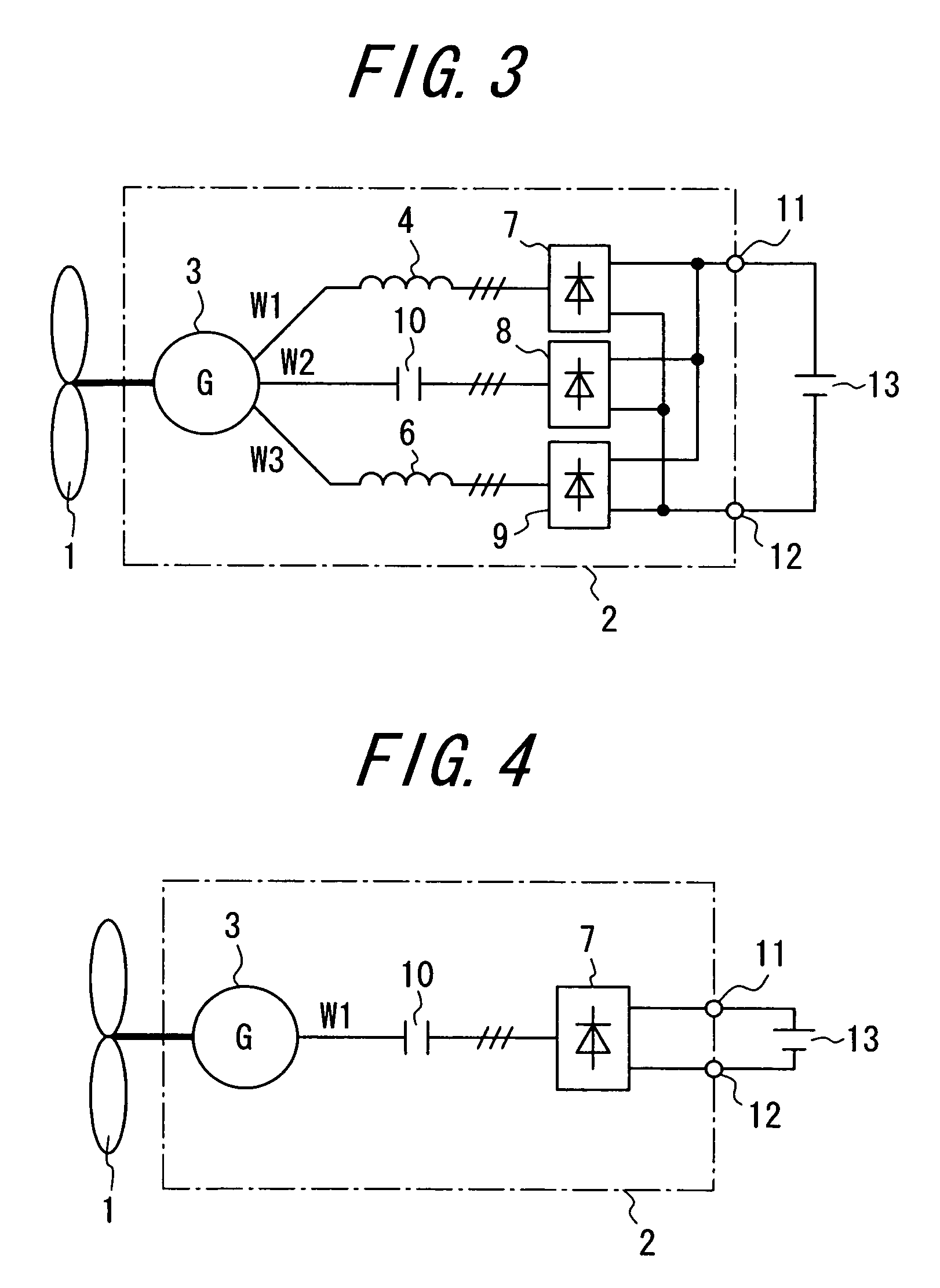
[0081]FIG. 3 illustrates the third embodiment of the invention.

[0082]FIG. 3 is a view illustrating the main circuit of an electric power generating apparatus 3 for dispersed power supply including a permanent magnet type electric power generator having three kinds of windings among which one kind winding has the second largest number of turns, to which the present invention is applied and whose alternating current output terminal has a capacitor connected thereto.

[0083]In FIG. 3, reference numeral 6 denotes a third reactor, and the same components as those in FIG. 2 are identified by identical reference numerals.

[0084]The third embodiment of the invention will be described with reference to FIG. 3 hereinafter.

[0085]A third reactor 6 and further a third rectifier 9 are connected in series to the alternating current output terminal W3 of the third winding having the largest number of turns.

[0086]A capacitor 10 and further a second rectifier 8 are then connected in series to the altern...


PUM


Abstract

In an electric power generating apparatus for dispersed power supply using a permanent magnet type electric power generator having many kinds of windings in order to obtain the maximum output by force of wind without using PWM converter, there is a problem that gap magnetic flux of the permanent magnet type electric power generator is demagnetized to decrease the internal induced voltage because alternating current output of the permanent magnet type electric power generator is lagging current. In an electric power generating apparatus for dispersed power supply including a permanent magnet type electric power generator having a plurality of windings inducing different effective values of induced voltages and individual rectifiers for rectifying alternating current outputs of the permanent magnet type electric power generator, a capacitor is connected in series between the individual rectifier and the alternating current output terminal of the winding inducing higher effective value of induced voltage among the plurality of windings in a manner that serial impedances of the capacitor and the permanent magnet type electric power generator become capacitive within the range of rated rotational speed of said permanent magnet type electric power generator.

Description

TECHNICAL FIELD[0001]This invention relates to a main circuit of an electric power generating apparatus for dispersed power supply, which derives from a permanent magnet type electric power generator driven by a windmill or waterwheel substantially maximum output obtained by wind or water irrespective of wind or water speed, and more particularly to a main circuit of an electric power generating apparatus for dispersed power supply for performing constant voltage charge from a permanent magnet type electric power generator without using a PWM converter.BACKGROUND ART[0002]In order to obtain the approximately or substantially maximum output from a permanent magnet type electric power generator connected to a windmill or waterwheel by converting alternating current to direct current without using a PWM converter, the applicant of the present application had proposed an electric power generating apparatus for dispersed power supply comprising a permanent magnet type electric power gene...

Claims


Application Information

Patent Timeline
Patent Type & Authority Patents(United States)
IPC IPC(8): F03B13/00F03B13/10H02P9/04H02M3/18
CPCH02J7/32H02K21/48H02M7/08H02P9/007H02P9/14H02P9/02F05B2220/7068H02P2101/15H02J3/386Y02E10/763H02J3/382H02P2101/10Y02E10/725H02J2300/28H02J2300/20H02J3/381Y02E10/72Y02E10/76
Inventor SHIOTA, TAKASHITANAKA, KEITAISAKA, TSUTOMU
Owner TOYO DENKI SEIZO KK
Why Eureka
Try Eureka