Integrated metal cosmetic strip to outerbelt, glass run, and upper reveal

a technology of cosmetic strips and metal strips, applied in the field of weather strips, can solve the problems of increasing assembly complexity, prohibitive cost of weather strips, and increasing so as to reduce the amount of expensive metal used, reduce the cost of weather strips, and facilitate manufacturing.

Inactive Publication Date: 2010-07-29
COOPER STANDARD AUTOMATIVE INC
View PDF14 Cites 19 Cited by
  • Summary
  • Abstract
  • Description
  • Claims
  • Application Information

AI Technical Summary

Benefits of technology

[0023]Another benefit resides in the decreased amount of expensive metal used in the completed weatherstrip.
[0024]Yet another benefit resides in the reduced costs of the weatherstrip.
[0025]Still further benefit is the ease of manufacture and the associated reduction in handling and assembly.

Problems solved by technology

Another issue with the use of a separate, mechanically joined cap is that a metal core and a separate metal show surface must be formed from a similar material or else a barrier must be provided between the materials.
Inclusion of a barrier layer further complicates the assembly and adds to the overall cost.
Thus, for example, if a stainless steel show surface is desired, it is necessary to then use stainless steel as the inside core material which makes the weatherstrip cost prohibitive.
Again, the addition of the barrier layer between the dissimilar metals adds undesired costs.
In addition, the use of caps become relatively expensive for at least two reasons.
First, the separate manufacture, inventory, handling, etc. of a clinch-on cap adds to the cost.
Secondly, subsequent assembly of the cap to the weatherstrip and the associated labor required to assemble the separate components drive the cost of the assembled weatherstrip to an undesired level.
As will be appreciated, however, this requires the use of the expensive metal throughout the entire weatherstrip and significantly increases the cost of the final component.

Method used


Image

  • Integrated metal cosmetic strip to outerbelt, glass run, and upper reveal
  • Integrated metal cosmetic strip to outerbelt, glass run, and upper reveal
  • Integrated metal cosmetic strip to outerbelt, glass run, and upper reveal

Examples


Embodiment Construction

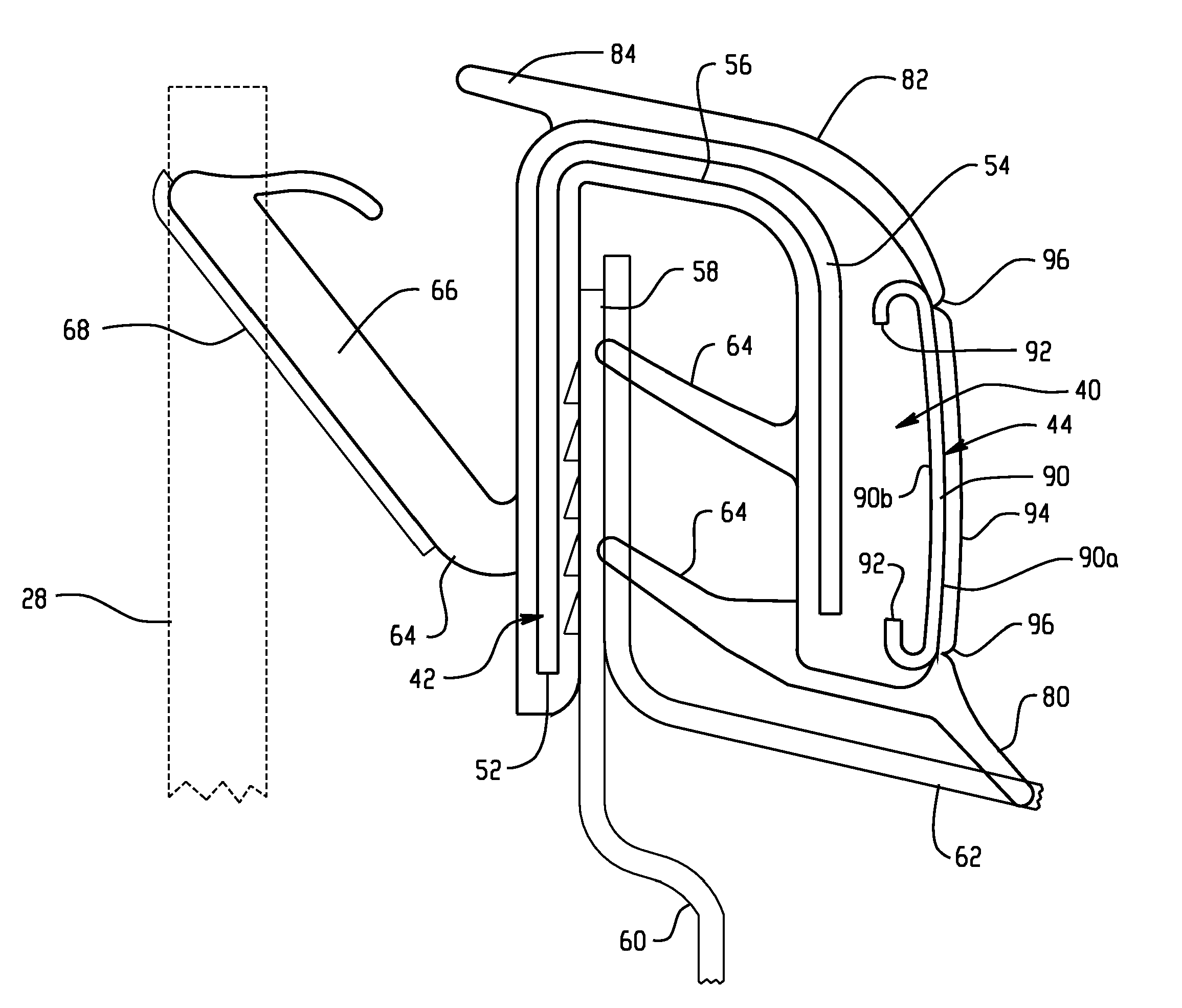
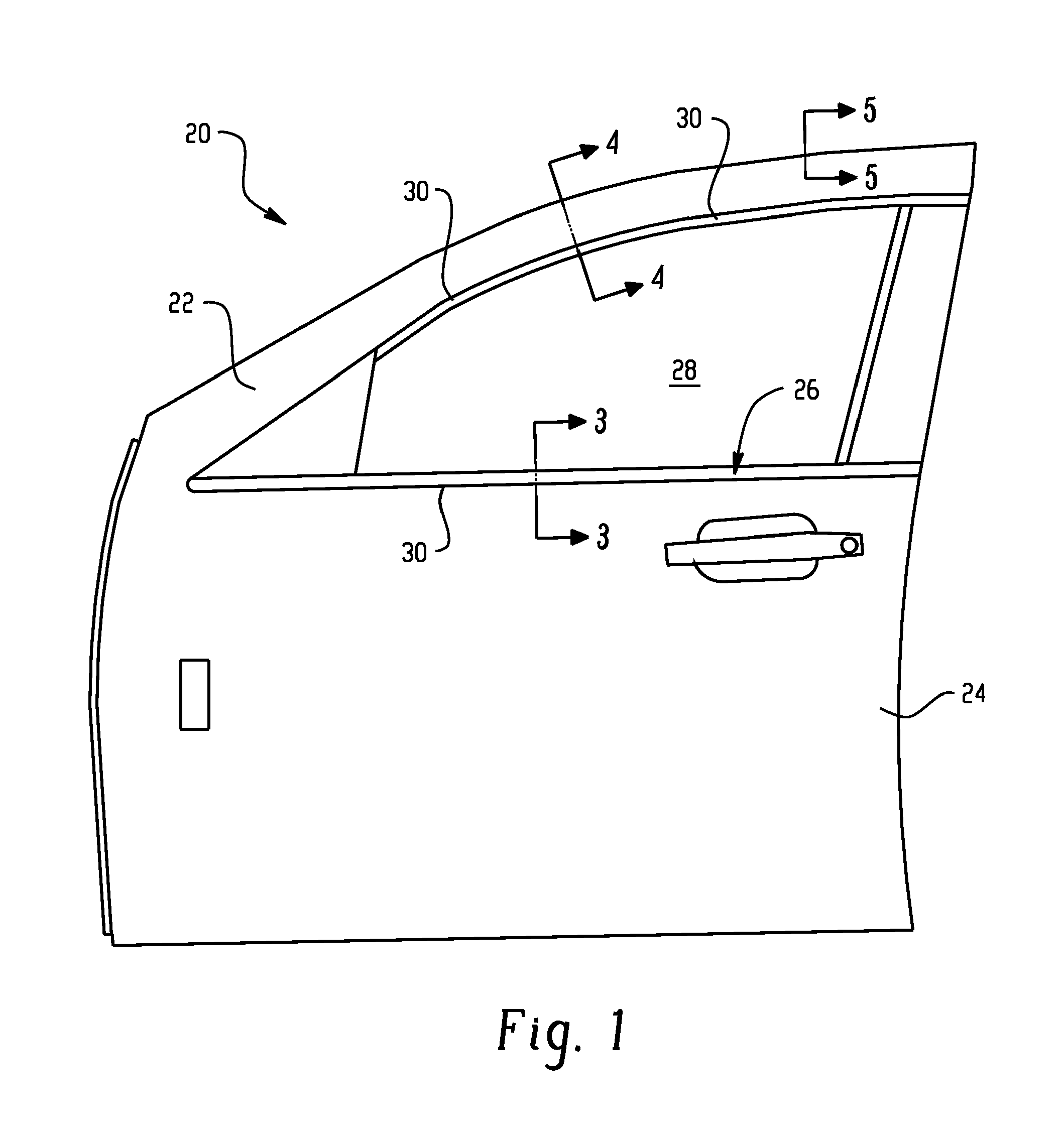
[0032]FIG. 1 illustrates an automotive vehicle 20 having a body 22 and a door, such as a front door 24 of the vehicle, which typically includes a window opening 26 that receives a movable window 28 that is selectively raised and lowered. As is well known, one or more weatherstrips 30 are provided on either or both the body 22 and the door 24 to thereby seal around an interface of the body and door, or around a window. In this manner, the interior compartment of the vehicle is not exposed to the external elements. This sealing function also includes sealing around the window opening 26 that receives the window 28.

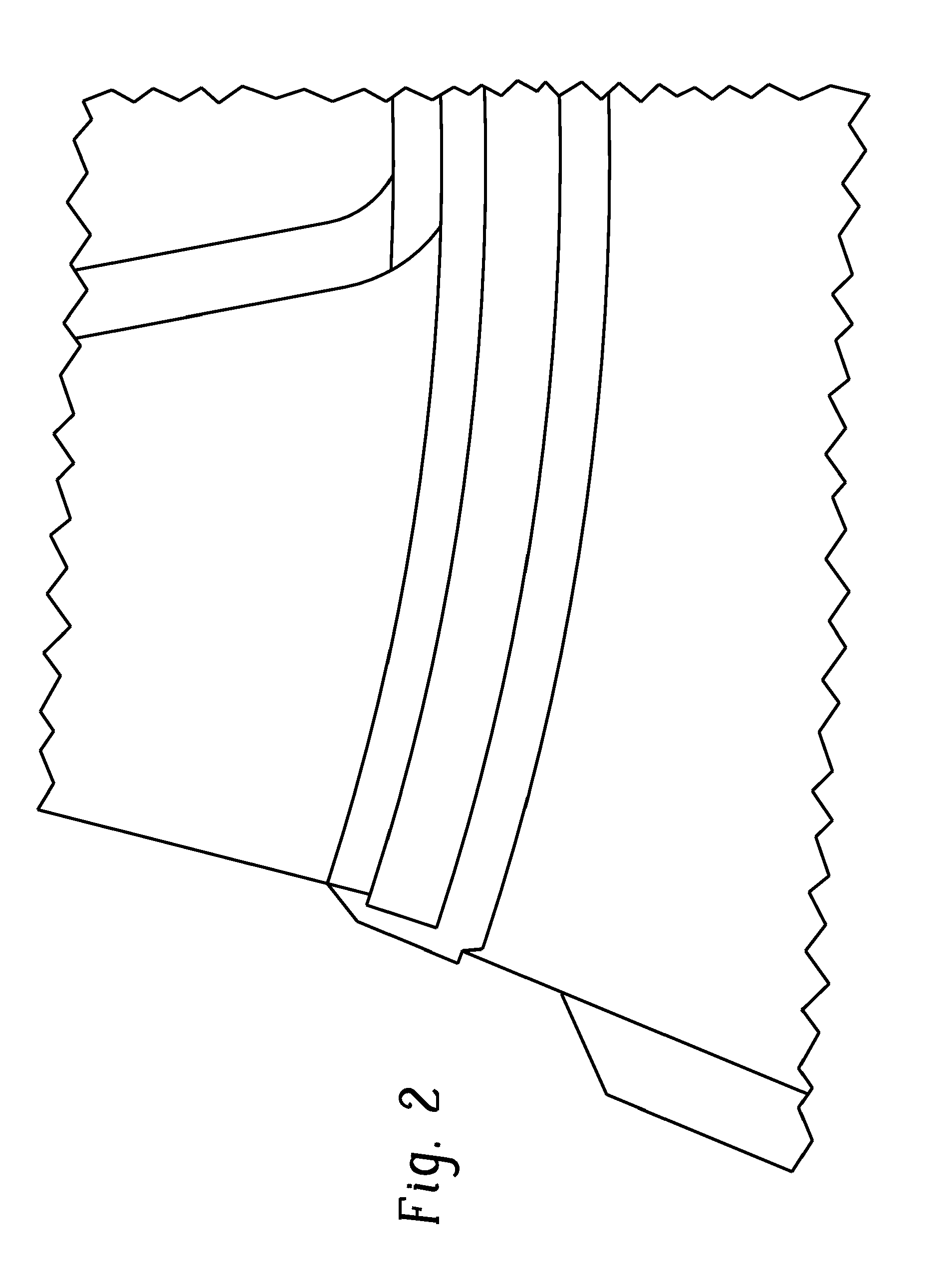
[0033]As noted in the Background, it is often desired by the OEM and customer to have a bright strip or show surface along selected regions of the vehicle. A common location for inclusion of these aesthetic accents is in association with the weatherstrip. While prior arrangements have been multi-part, and mechanically assembled arrangements that suffer from the deficiencies ...


PUM


Abstract

A weatherstrip (30) for an automotive vehicle includes a rigid core (42) formed from a first material encompassed in an extrusion body (40) of an elastomeric material. A show surface (44), such as anodized metal or stainless steel, is roll-formed and then coextruded in a coextrusion die with the rigid core. A removable layer (94) protects an outer face (90a) the show surface during extrusion and post processing steps of manufacture. The integrated arrangement of the cosmetic strip reduces manufacturing and assembly costs, while providing the desired aesthetic appearance to the weatherstrip.

Description

BACKGROUND OF THE INVENTION[0001]This application claims priority from U.S. provisional application Ser. No. 60 / 934,359, filed 13 Jun. 2007, the disclosure of which is expressly incorporated herein by reference.[0002]This disclosure relates to automotive vehicles, and more particularly to weatherstrips used in such vehicles. In addition to functional aspects of the weatherstrip, it is recognized that the aesthetics are also extremely important. Over the years, natural rubber, EPDM, and more recently thermoplastics have been used to form the weatherstrip body—generally referred to as an elastomeric material. It is also common to extrude the body from one of these materials because of the ease and reduced costs associated with this form of manufacture.[0003]One desired show surface provides a cosmetic or bright strip, such as a stainless steel or anodized metal that is joined to the elastomer. Heretofore, such assemblies are a multi-part assembly in which a rigid core is coextruded wi...

Claims


Application Information

Patent Timeline
Patent Type & Authority Applications(United States)
IPC IPC(8): E06B7/16
CPCB60J5/0402B60R13/04B60J10/75B60J10/74B60J10/265
Inventor DROZD, ERICMISTOPOULOS, JAMES
Owner COOPER STANDARD AUTOMATIVE INC
Why Eureka
Try Eureka