Barrier device, autostereoscopic display using the same and driving method thereof

a technology of display device and display device, which is applied in the direction of static indicating device, glass wing, instruments, etc., can solve the problems of display image giving a burden to the observer's eyes, difficult to view objects other than stereoscopic images, and inability to display 3d images on the screen

Active Publication Date: 2011-11-15
SAMSUNG DISPLAY CO LTD
View PDF13 Cites 8 Cited by
  • Summary
  • Abstract
  • Description
  • Claims
  • Application Information

AI Technical Summary

Benefits of technology

[0016]The barrier devices, the 3D image display devices, and the driving method thereof according to the exemplary embodiments of the present invention have a feature in that a pattern of a barrier can be changed according to the user's choice.

Problems solved by technology

As such, each stereoscopy method requires the inconvenience of wearing the spectacles, and causes difficulty of viewing objects other than the stereoscopic image.
The stripe type barrier has disadvantages in that a horizontal resolution is at most half of a vertical resolution, and a displayed image gives a burden to the observer's eyes because a vertical stripe pattern appears in the displayed image.
Therefore, the 3D images are not available on a screen of the landscape mode when a barrier for the portrait mode is combined with the display device.
However, the zigzag type barrier has a drawback of a narrow viewing angle whereas it has improved horizontal resolution.
Also, though it may be available for both of the portrait mode screen and the landscape mode screen, when the screen is changed to the landscape mode while the display mode of the barrier is fixed, a 3D image may not be displayed correctly depending on the position of left eye pixels and right eye pixels of the display panel, and the position of opaque regions and transparent regions of the barrier.
For those reasons, it has been difficult to popularize the 3D image display device.

Method used


Image

  • Barrier device, autostereoscopic display using the same and driving method thereof
  • Barrier device, autostereoscopic display using the same and driving method thereof
  • Barrier device, autostereoscopic display using the same and driving method thereof

Examples


Embodiment Construction

[0050]Certain exemplary embodiments of the present invention will hereinafter be described in detail with reference to the accompanying drawings.

[0051]In the following detailed description, only certain exemplary embodiments of the present invention have been shown and described, simply by way of illustration. As those skilled in the art would realize, the described embodiments may be modified in various different ways, all without departing from the spirit or scope of the present invention. Accordingly, the drawings and description are to be regarded as illustrative in nature and not restrictive. Like reference numerals designate like elements throughout the specification.

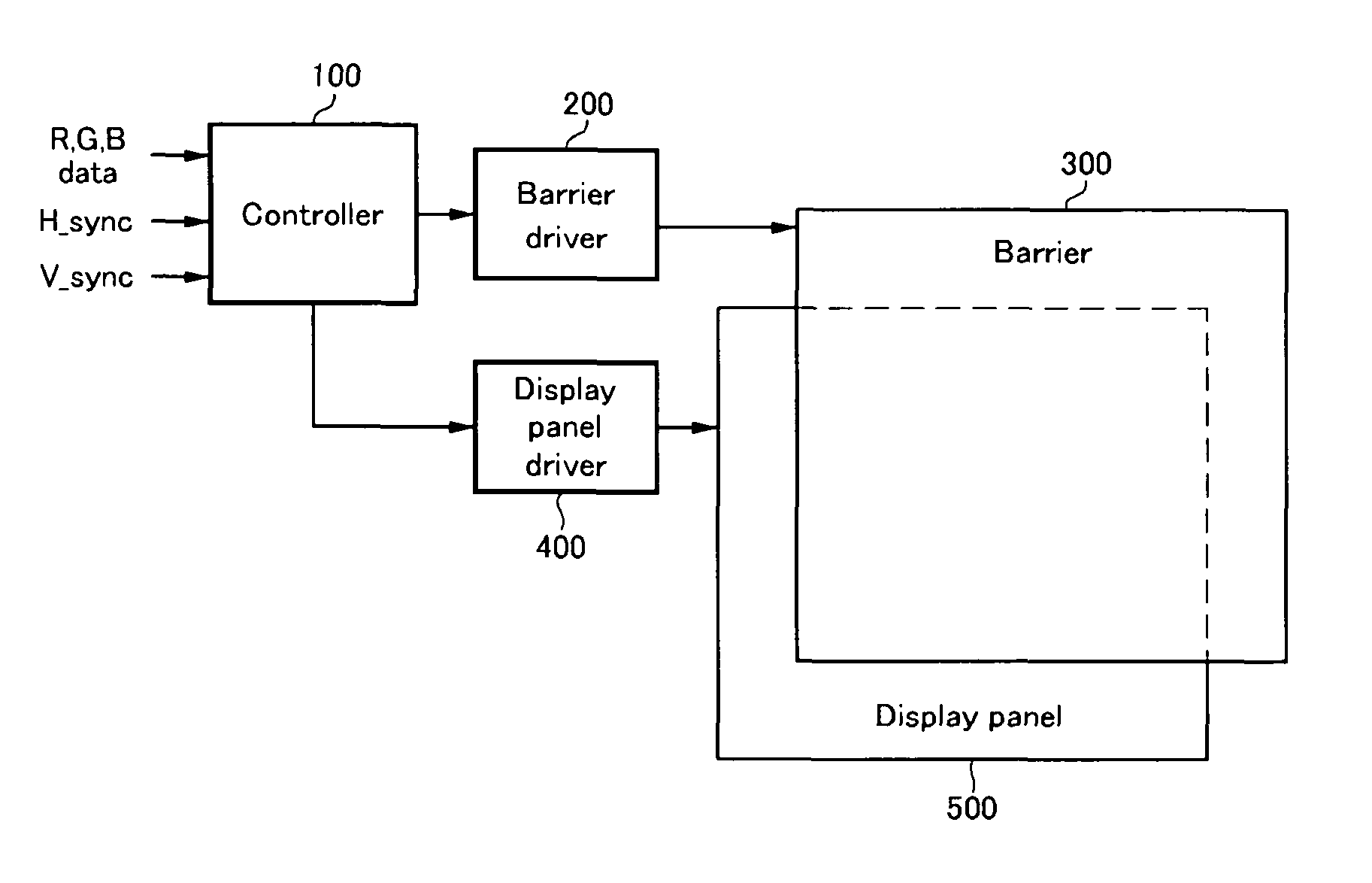
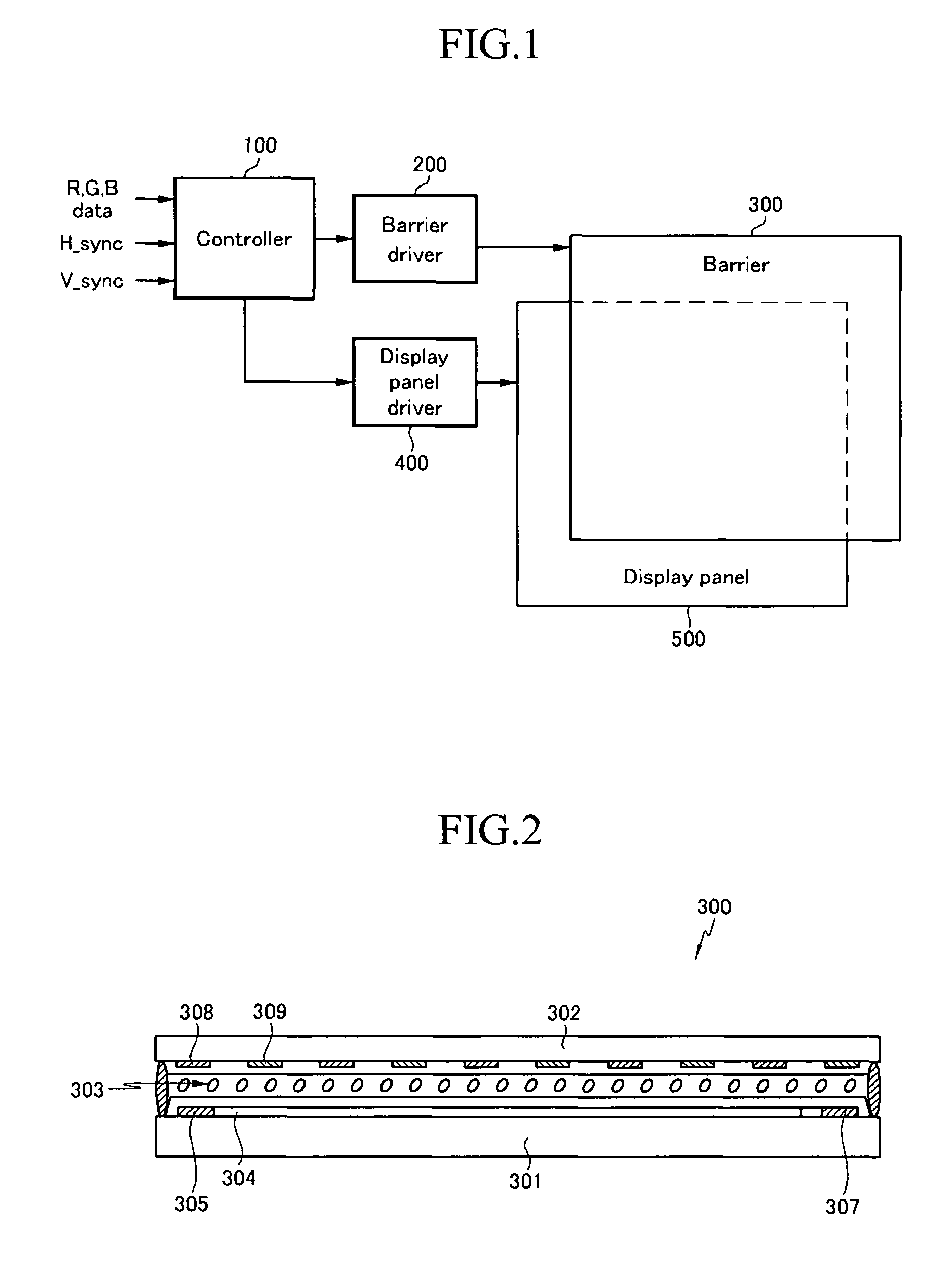
[0052]FIG. 1 shows a block diagram of a 3D image display device according to an exemplary embodiment of the present invention.

[0053]The 3D image display device includes a controller 100, a barrier driver 200, a barrier 300, a display panel driver 400, and a display panel 500.

[0054]The controller 100 generates a ba...


PUM


Abstract

A 3D image display device includes a display panel, a barrier, a controller, and a barrier driver. The barrier includes: a first substrate; a plurality of first electrodes disposed on the first substrate and extended in a first direction; a plurality of second electrodes respectively disposed between adjacent first electrodes; a second substrate opposing the first substrate; a plurality of third electrodes disposed on the second substrate and extended in a second direction crossing the first direction; a plurality of fourth electrodes respectively disposed between adjacent third electrodes; and a liquid crystal layer disposed between the first and second substrates. The barrier driver receives a barrier control signal from the controller, and applies a reference voltage to the first electrodes, the second electrodes, the third electrodes, and / or the fourth electrodes, and applies a liquid crystal driving voltage to one or more other ones of the first to fourth electrodes.

Description

CROSS-REFERENCE TO RELATED APPLICATION[0001]This application claims priority to and the benefit of Korean Patent Application No. 10-2005-0018210 filed on Mar. 4, 2005 in the Korean Intellectual Property Office, the entire content of which is incorporated herein by reference.BACKGROUND OF THE INVENTION[0002]1. Field of the Invention[0003]The present invention relates to a barrier device and a 3D image display device using the same for displaying a 3D image by using binocular disparity. More particularly, the present invention relates to a barrier device and a 3D image display device using the same, which are able to change barrier shape.[0004]2. Description of the Related Art[0005]In general, people perceive a stereoscopic effect physiologically and experientially. In three-dimensional image display technology, a stereoscopic effect of an object is produced by using binocular parallax, which is a primary factor in recognizing a stereoscopic effect at a short distance. Stereoscopic im...

Claims


Application Information

Patent Timeline
Patent Type & Authority Patents(United States)
IPC IPC(8): G09G3/36
CPCH04N13/0409H04N13/0497H04N13/31H04N13/398E05Y2800/41E06B3/02E06B7/215E06B7/36
Inventor NAM, HUILEE, JANG-DOOJANG, HYOUNG-WOOKKIM, BEOM-SHIKSONG, MYOUNG-SEOP
Owner SAMSUNG DISPLAY CO LTD
Why Eureka
Try Eureka