Rotating toner cleaning member for a toner delivery device in an image forming apparatus

a toner delivery device and rotating technology, applied in the direction of electrographic process apparatus, instruments, optics, etc., can solve the problems of insufficient toner transfer, inconvenient toner delivery, and insufficient toner transfer, so as to prevent toner buildup.

Active Publication Date: 2011-11-15
LEXMARK INT INC
View PDF22 Cites 5 Cited by
  • Summary
  • Abstract
  • Description
  • Claims
  • Application Information

AI Technical Summary

Benefits of technology

[0026]Advantageous aspects of the invention reside in the prevention of toner buildup on the surfaces of the toner transfer mechanism. The amount of toner transferred by the toner transfer mechanism in each transfer event is therefore substantially consistent. The invention utilizes existing rotating members in the sump of a cartridge structure to support a member for cleaning the rotor surfaces of the toner transfer mechanism on each rotation of the rotor which results in more consistent delivery of toner, without substantial modification to the toner transfer mechanism within the cartridge structure.

Problems solved by technology

In the event that the toner contained in the cartridge has poor flow properties, the toner transfer mechanism alone may not properly, sufficiently and consistently transfer toner from the toner storage reservoir to the working reservoir.
The toner may build up on the surfaces of the toner transfer mechanism with the result that the amount of toner transferred by the transfer mechanism is not consistent from one transfer event to another also referred to a toner metering cycles.
Estimating toner consumption and cartridge life can therefore be problematic and toner transfer may become insufficient to sustain acceptable print quality.

Method used


Image

  • Rotating toner cleaning member for a toner delivery device in an image forming apparatus
  • Rotating toner cleaning member for a toner delivery device in an image forming apparatus
  • Rotating toner cleaning member for a toner delivery device in an image forming apparatus

Examples


Embodiment Construction

[0034]The present invention will now be described more fully hereinafter with reference to the accompanying drawing figures, in which some, but not all embodiments of the invention are shown. The invention may be embodied in many different forms and should not be construed as limited to the embodiments set forth herein; rather, these embodiments are provided so that this disclosure will satisfy applicable legal requirements.

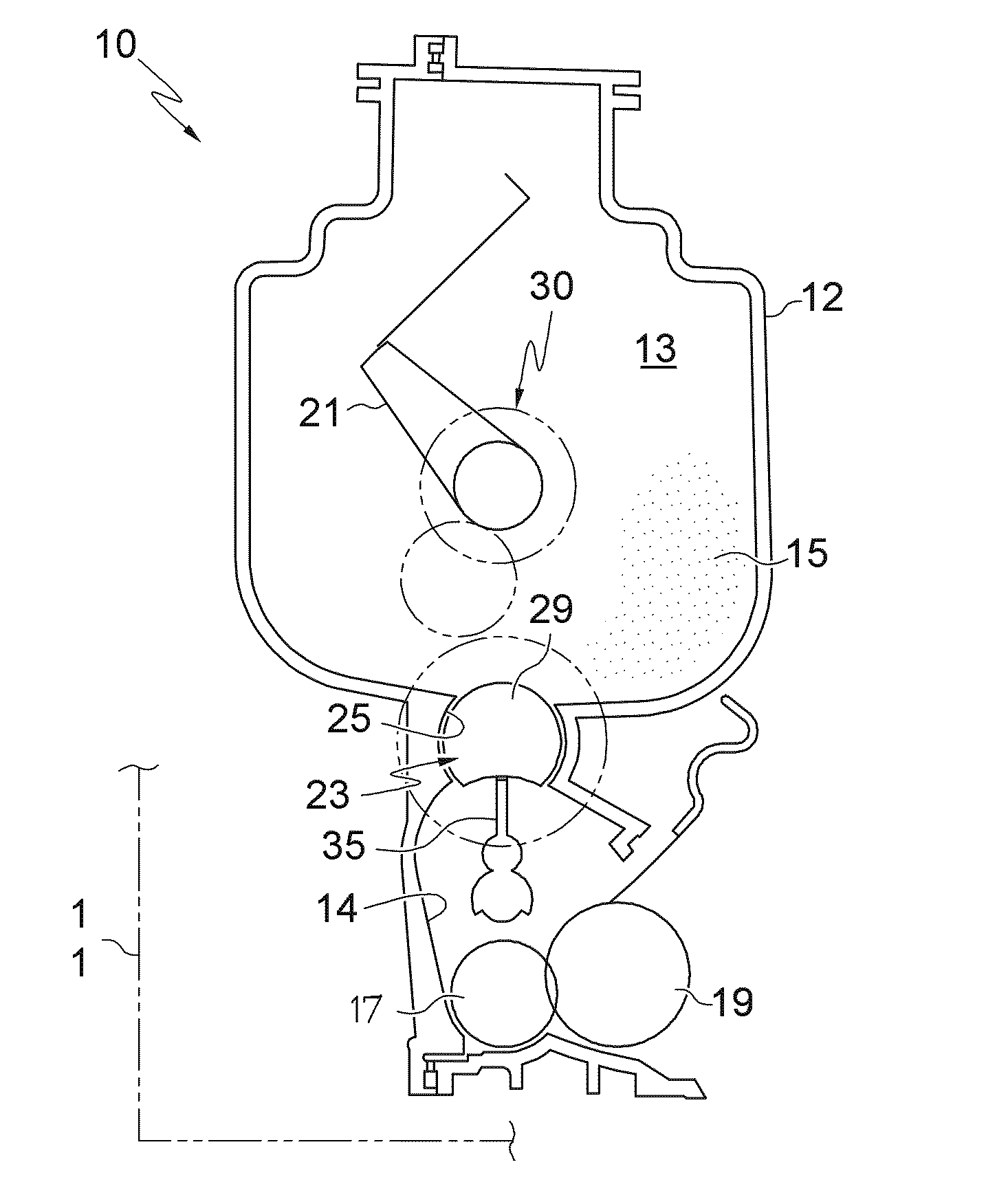
[0035]Reference is now made to the Campbell et al. '291 patent for a description of the basic elements and operation of the overall electrophotographic image forming process in a typical image forming apparatus utilizing a plurality of color cartridges. Specific reference is made to FIG. 1 of Campbell et al. '291 and the accompanying text briefly describing the structure and operation of a four cartridge color laser printer as a non-limiting exemplar of image forming devices generally using toner for printing with a photoconductor.

[0036]Reference is also made to ...


PUM


Abstract

The present invention provides a toner container system, such as a toner cartridge, comprising a housing including a first reservoir for containing toner and a second reservoir for receiving toner from the first reservoir and transferring the toner to an image forming apparatus, and a toner transfer mechanism that includes a rotatable roller member having in the surface thereof a recess defined by a concave surface having a radius of curvature, and wherein the roller member is rotatable from a first position at which the recess is open to the first reservoir and a second position at which the recess is open to the second reservoir, for conveying toner from the first reservoir to the second reservoir upon rotation of the roller member from the first position to the second position, and a rotatable wiper member disposed within the second reservoir and being sized and having a flexible distal end rotatable through the recess in contact with the concave surface when the roller member is in the second position.

Description

CROSS REFERENCE TO RELATED APPLICATIONS[0001]Cross-reference is made to copending U.S. patent application Ser. No. 12 / 424,921, filed Apr. 16, 2009 entitled “Geneva Drive And Locking Mechanism Therefor In A Toner Metering Mechanism For An Image Forming Apparatus” and assigned to the assignee of the present invention.BACKGROUND OF THE INVENTION[0002]1. Field of the Invention[0003]The present invention relates to toner container structures for image forming devices, and more particularly to a toner container structure having a rotating toner transfer mechanism that includes a rotating member for cleaning toner from the surfaces of the toner transfer mechanism.[0004]2. Description of the Related Art[0005]Image forming devices including copiers, laser printers, facsimile machines, and the like, include a photoconductive drum having a rigid cylindrical surface that is coated along a defined length of its outer surface. The surface of the drum is charged to a uniform electrical potential a...

Claims


Application Information

Patent Timeline
Patent Type & Authority Patents(United States)
IPC IPC(8): G03G15/08
CPCG03G15/0877
Inventor GAYNE, JARRETT CLARKKERN, ROYDEN THOMAS
Owner LEXMARK INT INC
Why Eureka
Try Eureka